Pt.0 (はじめに) の続きです。
This article is a sequel to “Things I learned on Phono EQ curves, Pt.0”.
レコードのEQカーブについて深掘りする前に、そもそも なぜイコライゼーションが生まれたのか、なぜ必要とされたのか、その歴史から調べてみることにしました。また、更にさかのぼって、音を溝に記録するとはどういうことか、についても学び直すことにしました。なので、カーブの話に到達するまでに長い道のりになってしまう予定です(笑)
Before digging deeper about EQ curves, I started to study from the very beginning: why the EQ curve was born, why it was/is needed for phonograph recording (and playback). Also, I tried to re-study the very basic – how the recording sounds are converted to a modulated spiral groove. So I’m afraid it will take very long before I reach the story of the EQ curve itself…

Audio Reconstruction of Mechanically Recorded Sound by Digital Processing of Metrological Data – Scientific Figure on ResearchGate.
Available from: https://www.researchgate.net/figure/Digital-image-of-the-surface-of-78-rpm-record-taken-with-optical-magnification-The_fig1_242606860 (accessed 4 Sep, 2022)
前回も書きましたが、筆者自身の学習過程を記したものですので、間違いの指摘や異論は遠慮なくお寄せください。
As I noted in the previous article, this is the footsteps of my own learning process, so please let me know if you find any mistakes on my article(s) / if you have different opinions.
相当長い文章になってしまいましたので、さきに要約を掲載します。同じ内容は最後の まとめ にも掲載しています。
This article become very lengthy – so here is the summary of this article (the same contents are avilable also in the the summary subsection).
レコードに音溝を記録する際、基本的には定速度特性で記録される
When a sound groove is cut on the record master, basically it has a constant-velocity characteristics.
全周波数帯域を定速度特性で記録すると、低域では溝が横に広がりすぎ、片面に記録可能な時間が短くなってしまう。また、高域では溝の振幅が小さくなりすぎ、サーフェスノイズに埋もれてしまう。
If the constant-velocity recording is applied to all the frequency range, two issues arrise: in low frequency range, groove excursion becomes much wider, resulting a short playing time for each side of a record; in high frequency range, the amplitude is too low to cope with surface noise.
そこで世界初の電気録音において、250Hzあたりから下は定振幅特性で、それより上は定速度特性で記録された。切り替わり周波数をベースターンオーバー周波数と言う。
When the first electrical recording was invented, ranges below around 250Hz had constant-amplitude characteristics, and for above around 250Hz constant-velocity charactieristic. The point where the transition from constant amplitude to constant velocity is called bass turnover frequency.
電気録音最初期においては、記録可能な高域上限はせいぜい4,500Hz〜5,500Hzであったため、当時はそれ以上の帯域はサーフェスノイズに対抗するためもあって急速減衰(定加速度特性)で記録された。そもそも、当時のスピーカでは高域まで再生できなかった。
In the early electrical recording days, the highest possible frequency that could be recorded was 4,500Hz to 5,500Hz at most, so the higher range was rapidly attenuated with constant-acceleration characteristics to cope with surface noise. Also, loudspeakers in this era could not reproduce higher frequencies in the first place.
これら録音記録特性は、現代のように電気回路で実現するのではなく、当時は各種構成部品の物性を活用して実現された。Bell Labs / Western Electric の最初の電気録音発明者である Maxfield & Harrison によって、電気回路のシステムと等価な機械システムを構成するアナロジーが確立され、のちのスピーカ技術発展にも貢献した。
These recording characteristics was accomplished by fully utilizing physical properties of all the elements and parts of the recording equipment, unlike recent decades when the recording curve is fully controlled by a dedicated electrical circuits. Maxfield & Harrison, inventors of Bell Labs / Western Electric’s first electrical recording system, made of the analogies between the electrical and the mechanical systems, that later contributed the evolution of loudspeakers as well.
電気録音誕生当時の再生はアコースティック機器で行われ、低域増幅(いまでいう再生カーブ)はロガリズミックホーンを用いて行われた。
When the electrical recording was born in 1925, the playback compensation (that is similar to what we now call “playback curve”) was done with logarithmic horn of the acoustic player.
Contents / 目次
1.1 Relearning Velocity and Amplitude / 速度と振幅を学び直す
さて、前置きが長くなりましたが、ここからやっと本題です。自分自身用の整理を兼ねて、自明なことまで改めて書いていくことになりますので、ご了承ください。
Well, the introduction part became longer than I initially planned, but anyway here it goes. Please note that I will be writing virtually everything I have learned – even obvious and trivial things – in order to organize my thoughts and opinions.
まずは、ディスク録音やイコライジングカーブの話をする際、あらゆる文献や解説に登場する “constant velocity” と “constant amplitude” について理解する必要があります。電気・機械工学のエッセンスから勉強しなおし、ですね(笑)
Now I’m going to start relearning from the basics of electric circuit – to understand the important terms “constant velocity” and “constant amplitude“, both of which always appear on any books and papers regarding audio disc recording / EQ curves. It’s just like learning the essence of the Electromechanical Engineering… 🙂
source: “National Audio Handbook”, p.2-26 (1976); archived at bitsavers.org
ナショナルセミコンダクター社が1976年に発行した “Audio Handbook” より。
“2.11 Phono Preamps and RIAA Eaualization” 節、p.2-26
1.1.1 Constant Velocity Recording & Playback / 定速度(等速度)記録再生
電気録音の場合、レコード原盤に記録(カッティング)する際には、空気の振動がマイク(かつてはトランスミッタと呼ばれていました)によって電気信号に変換され、アンプで補正されたり増幅されたりした信号がカッターヘッドに送られ、溝を記録します。そしてレコードを再生する際には、フォノカートリッジの針が溝をトレースすることで、物理的振動が電気信号に変換され、イコライザやアンプを経由して、スピーカを駆動し、最終的に空気振動に戻されます。
In the Electric Recording, vibrations of the air are converted to the electric signals with microphones (or previously “transmitters”), then the signal being compensated and amplified with amplifiers in order to feed to the recording cutter, then the cutter cutting a long line of spiral groove on the disc. And when in reproduction, the stylus of the phono cartridge traces the groove on the record, converting physical vibrations to electric signals, then the signal being compensated and amplified with amplifiers to drive speaker units – in this way the groove frequency (the stylus movement) finally becoming back to the vibrations of the air.

source: “Improvements in Disc Records Through Constant Amplitude Recording”, Communications, pp.13-14&28, March 1940
さらに古いアコースティック録音の場合、ホーンで集められた空気の振動が直接ダイアフラムを動かし、そこに接続された針が回転する原盤に溝を刻みます。再生も、ダイアフラムに接続された針が溝をトレースすることで、物理的振動を直接空気振動に変換し、ホーンを通して増幅されます。
In the earlier Acoustic Recording, vibrations of the air are fed through the parabolic reflector (recording horn), driving the diaphragm directly, and the recording stylus that is directly connected to the diaphragm cuts the groove. And when in reproduction, the stylus on the diaphragm traces the groove, converting the mechanical vibrations to the vibrations of the air, which finally is amplified through the horn.
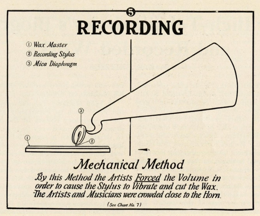
source: “Brunswick Electrical Recording ”, Elmer C. Nelson, The Phonograph Monthly Review, Vol.1; No.1, pp..19-21, October 1926.
録音→再生のこの一連の流れで登場する「トランスデューサ」(空気振動→音溝、音溝→電気信号、など、あるエネルギーを別のエネルギーに変換する装置)では、基本的(あるいは理想的)には 定速度 (または等速度, constant velocity) という特性を備えています。
These transducers (from aerial vibration to recorded grooves, grooves to electric signals, etc.) – that appear during these recording-reproduction chain – basically (or ideally) have constant velocity characteristics.
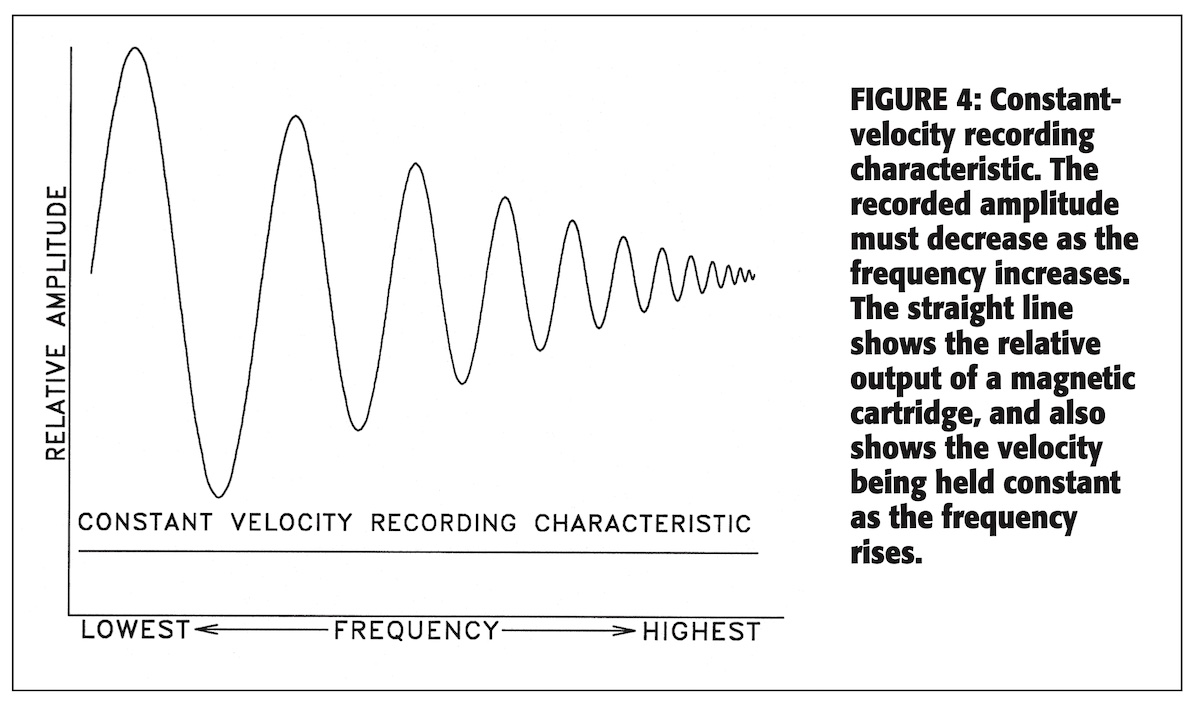
source: “Disc Recording Equalization Demystified”, by Gary A. Galo, The LP Is Back!, pp.45-54, audio express website (1999)
定速度で記録された波(音溝)と、定速度特性のピックアップで再生した際の出力レベル、のイメージ
実際には、カッターヘッドには共振周波数というものが存在し、なにも補正しない状態では、特定の周波数をピークに山なりの尖った特性カーブになります。これを素材でダンピングしたり、フィードバックをかけたりして、定速度的にフラットに近づける工夫が施されています。
Actually the cutterhead has its own resonance frequency, and its uncompensated frequency response becomes the sharp shape of an arch. So several techniques like damping, feedback circuits, etc. are employed to accomplish the desired flat frequency response.
定速度特性では、一定の入力レベルであるとするならば、周波数が高くなればなるほど、振幅は小さくなり、逆に周波数が低くなればなるほど、振幅は大きくなります。1オクターブあがれば(=周波数が倍になれば)、振幅は半分(音圧は-6dB)になり、1オクターブさがれば(=周波数が半分になれば)、振幅は2倍(音圧は+6dB)になります。
In the constant velocity characteristics, if the input is constant regardless of frequency, the amplitude of the waves in the groove becomes narrow as the frequency goes up; wave amplitude becomes wide as the frequency goes down. One octave up becomes the half of the width of the wave (-6dB sound pressure); One octave down doubles the width (+6dB sound pressure).
定速度特性のマグネティックカッターにより、レコード原盤上のらせん上の溝の振幅となって刻まれるわけですから、同じく定速度特性のピックアップ(マグネティックカートリッジ)によって再生すると、イコライジング不要でフラット再生できる、というわけです。
If the entire disc is cut by the magnetic cutter that has constant velocity characteristics, tracing that spiral groove by a constant pickup with constant velocity characteristics will (ideally) result in “flat” playback – without any compensation.
アコースティック録音の時代(〜1925)は、基本的には定速度記録になっていて、記録可能な周波数帯域はせいぜい 250Hz〜2,500Hz 程度と言われていました。ちなみに、アナログ固定電話の周波数帯域は 300Hz〜3,400Hz ですから、比較的近いですね。
In the Acoustic Recording years (-1925), it was basically constant velocity, and is said that 250Hz to 2,500Hz was the best possible frequency range that was recorded. By the way, analog fixed-line phone can transfer 300Hz to 3,400Hz, which is somewhat similar to the acoustical recordings.
Audacity wiki の アコースティック録音ディスク のセクションでは、興味深い複数の説について触れられており、ダイアフラムの物理特性や録音用の集音器(ホーン)の音響特性がからむため、必ずしも適合する再生特性が定速度とは言い切れないのではないか、という意見もあるようです。ただし、録音装置と全く同じ再生装置であれば、フラット再生はほぼ保証されるのでしょう。
According to the Acoustic recording and Broadcast Transcription Discs section in the Audacity wiki, several interesting opinions are introduced. One says that acoustic recording was not always the constant velocity because of physical characteristics of diaphragm and parabolic reflector (recording horn). However, I guess that, if the playback was done with the very same recording equipment, it would play nearly flat on all recorded frequency range.
しかし、Bell Telephone Laboratories (B.T.L.、以下 Bell Labs) の J.P. Maxfield と H.C. Harrison によって発明され1925年に実用化、そしてその後発展していった 電気録音 (Electrical Disc Recording) では、記録可能な周波数帯域がどんどん広がっていきました。
However, as time went by, and as the technology continued improving, the Electrical Disc Recording that originally was invented by J.P. Maxfield and H.C. Harrison of Bell Telephone Laboratories (or B.T.L., or Bell Labs) and made practical in 1925 could record wider frequency range.
なんと、電気録音発明者の1人である Joseph P. Maxfield 氏に行った、1973年の口頭インタビュー がまとめられていました。Maxfield 氏の肉声も聞ける、非常に貴重な資料です。
I was surprised when I found this – An oral interview with Joseph P. Maxfield, one of the men who invented Electrical Disc Recording, conducted in 1973. You can listen to his own voice on this webpage, and it’s definitely invaluable.
特に、より低域まで記録できるようになったことで、この定速度記録で溝を刻むと「隣の溝とぶつかってしまうほど溝の幅が広くなってしまう」「それを避けるには、溝のピッチを極端に広げる必要がある = 片面に記録可能な時間が減ってしまう」という問題が発生することになりました。
As a result, because it can record lower frequency range, constant velocity recording could result in excessive groove excursion and causing cross over between tracks. In order to prevent this issue, it is needed to lower the grooves-per-inch (g.p.i.).
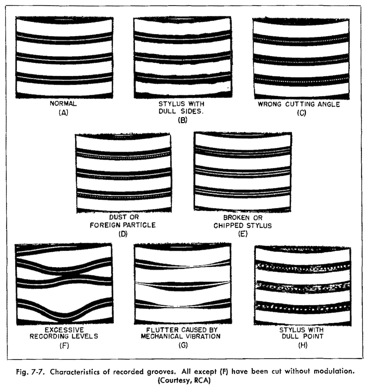
source: “The Recording and Reproduction of Sound”, by Oliver Read, p.108, Howard W. Sams & Co., Inc. (1952)
この図はLP時代のものですが、図 (F) のような状態が「隣の溝とぶつかった」ものです
These figures are from the “microgroove” LP era, but anyway the figure (F) is a similar image of the groove excursions becoming too large (although this image is a result of excessive recording levels).
例えば、1,600Hz を記録した音溝の振幅を基準にすると、同じレベルの 200Hz の振幅は 23 = 8倍になってしまいます。100Hz だと 24 = 16倍、50Hz だと 25 = 32倍です。
For example, compared with the groove excursion width of 1,600Hz, that of 200Hz (at the same level of 1,600Hz) would become 23 = 8 times wider; that of 100Hz would become 24 = 16 times wider; that of 50Hz would become 25 = 32 times wider.
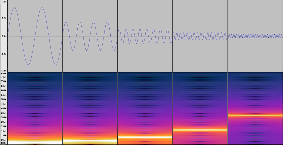
「定速度」のイメージ図、200Hz, 400Hz, 800Hz, 1,600Hz, 3,200Hz、Audacityを使って作成
Image of “constant velocity”, 200Hz, 400Hz, 800Hz, 1,600Hz, and 3,200Hz, generated using the Audacity software.
また、電気録音最初期は 4,000Hz 程度までしか記録していなかったので問題になりませんでしたが、時代が進んでより高域まで記録できるようになると、高域では記録振幅が小さくなりすぎてしまいます。先ほど同様 1,600Hz を基準にすると、6,400Hzの音溝の幅は 2-2 = 1/4倍に、12,800Hzの場合は 2-3 = 1/8倍になります。
Also, being capable of recording much higher frequencies would result in narrower groove width (amplitude) in such high frequency range. Again, compared with the groove width of 1,600Hz, that of 6,400Hz would become 2-2 = one-fourth; that of 12,800Hz would become 2-3 = one-eighth. This was not a serious problem in the early years though, as the highest recorded frequency was about 4,000Hz at most.
そのため、せっかく記録した高域の溝なのに、レコードと針がこすれることにより生じるサーフェスノイズにマスクされ埋もれてしまうことになります。
Because of this, the amplitude of the high frequency groove is not wide/large enough to compete with the “surface noise”.
1.1.2 Constant Amplitude Recording / 定振幅(等振幅)記録
そこで、周波数の高低に関わらず、同じ入力レベルであれば、溝の幅を同じにする、という記録方法もあります。定振幅 (または等振幅, constant amplitude) です。こうすることで、上で触れた「低音により溝の幅が広くなってしまう」「それを避けるために溝のピッチを極端に広げる必要がある」を解決できることになります。
There is another way of converting sounds into waved grooves: if the signal is at the same level for all frequencies, the recorded groove width (amplitude) is the same for all frequencies. This is constant-amplitude recording. This will solve “excessive groove excursion at low frequencies” and “the need for lowering the grooves-per-inch”.
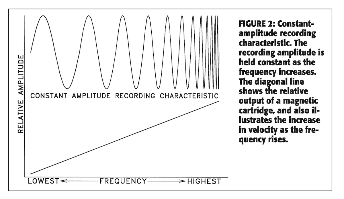
source: “Disc Recording Equalization Demystified”, by Gary A. Galo, The LP Is Back!, pp.45-54, audio express website (1999)
定振幅で記録された波(音溝)と、定速度(等速度)特性のピックアップで再生した際の出力レベル、のイメージ
この定振幅で記録されたディスクを、クリスタルカートリッジやセラミックカートリッジといった、定振幅特性を備えた圧電カートリッジで再生する場合は、補正がほとんどいらなくなります。
If you play a “cut by constant-amplitude” disc with crystal/ceramic (piezo-electric) phono cartridges (that are constant amplitude devices), there is virtually no need for any compensations.
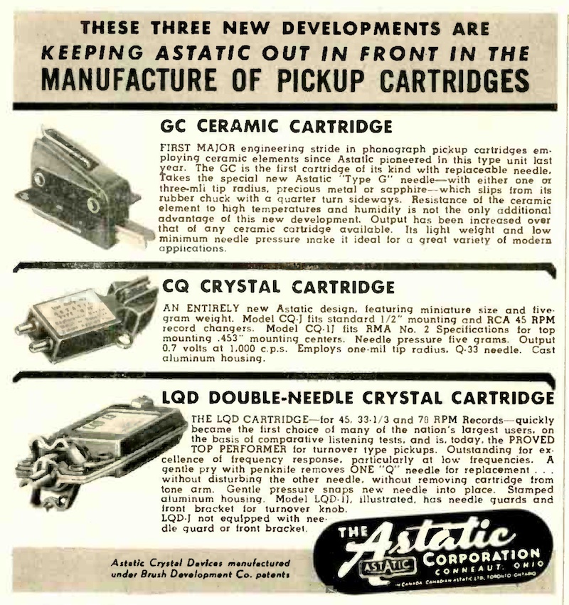
source: The Astatic Corporation Ad, Audio Engineering, October 1, 1949, p.42.
Audio Engineering 誌 1949年10月1日号掲載、Astatic 社のクリスタル/セラミックカートリッジの広告
Crystal/Ceramic Cartridges Ad on Augio Engineering Magazine, Oct. 1, 1949.
しかし、現在一般的なMM/MC/MI型などの定速度特性を備えたカートリッジで再生すると、記録された本来の音にならず、低域になればなるほど小さく、高域になればなるほど大きく再生されることになりますので、再生時に補正が必須となります。
However, vast majority of us are using MM/MC/MI phono cartridges (that have constant velocity characteristics) nowadays, and if you play constant-amplitude discs with constant-velocity phono pickups, the low frequency range sounds less than intended, and the high frequency range sounds more than intended – so you need to apply some compensations.
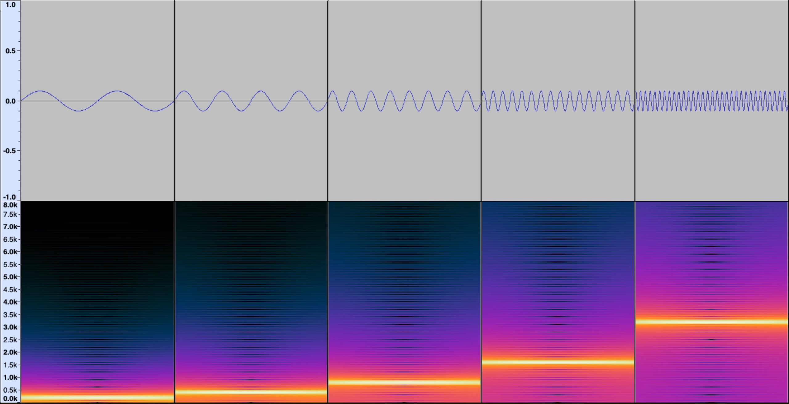
「定振幅」のイメージ図、200Hz, 400Hz, 800Hz, 1,600Hz, and 3,200Hz、Audacityを使って作成
Image of “constant amplitude”, 200Hz, 400Hz, 800Hz, 1,600Hz, and 3,200Hz, generated using the Audacity software.
また、この定振幅記録では、高域の溝の振幅も一定になりますので、高音域の音溝の曲率半径が小さくなってしまい、再生時に針が正確にトレースできなくなってしまいます(この辺の詳しい話は Pspatial Audio Stereo Lab の “Maximum recorded velocities” というページ で説明されています)。
Also, as mentioned, constant amplitude recording means constant groove width for all frequencies (if the input volume is the same for all frequencies) – this will result in the recorded groove having “too low radius curvatures” for the pickup’s stylus to track every groove wall correctly. You may want to read more technical details about this in the “Maximum recorded velocities” article at the Pspartial Audio Stereo Lab website.
ましてや、レコードが78rpm(より正確には78.26rpm)という高速で回転し、かつダイアフラムに取り付けられた鉄針が100g〜200gの重さでレコードに押し付けられている、というアコースティック〜電気録音最初期の再生環境ですから、溝を正確にトレースできないだけではなく、せっかく高音域を微細な音溝で記録できていたとしても、再生のたびにどんどん削れていってしまいます。
What’s more, in these “Acoustic” years and “Early Electric” days, old phonograph records are spinning at very high speed – 78rpm (more precisely, 78.26rpm) – a very heavy pickup and steel needle tracine the groove on the records, with very heavy pressure at 100g to 200g. This will result inaccurate groove tracing, and what’s worse, high-frequency grooves (with low radius curvatures) will be destroyed by the heavy steel needle.
1.1.3 Intuitive metaphor of constant {velocity, amplitude}
/ 定{速度,振幅}の直感的な比喩
ちょうど、PS Audio 社の「Revolutions Per Minute: Vinyl and Absolute Polarity: Q&A」というブログ記事で、録音エンジニア J.I. Agnew 氏がこの「定速度」「定振幅」についての興味深い(単純化した・直感的な)比喩を記しているのを見つけましたので、ここに引用しておきます。
Recently I came accross a very interesting article “Revolutions Per Minute: Vinyl and Absolute Polarity: Q&A” at PS Audio’s blog. It contains a very interesting (simplified and intuitive) metaphor to descrive “constant velocity” and “constant amplitude” – and here I’m quoting from the article:
To better understand constant amplitude versus constant velocity, take a 12-inch record sleeve as a reference and slowly move your hand back and forth by 12 inches. Now do it faster, as fast as you can. It gets harder the faster you go.
定振幅と定速度について、より理解するために、こんなことをやってみましょう。12インチレコードのジャケットを目安として、手を12インチだけ左右にゆっくり動かしてみてください。次に、同じことを可能な限り速くやってみましょう。手の動きを速くすればするほど、大変になってきますよね。
Now allow your hand to reduce the amplitude to less than 12 inches, and you will notice that the faster you go, the lower the amplitude will tend to be. This is constant velocity, or as an over-simplification, constant effort. Constant amplitude requires that the amplitude remains constant (the full 12 inches) as your hand velocity increases (you’re moving it faster), which requires increasing effort, but keeps that motion clearly visible relative to the background, even from a distance. This results in an improved signal to noise ratio.
ではここで、手を動かす幅を12インチより狭くしていいことにしましょう。そうすると、手を速く動かそうとすればするほど、手を動かす幅がどんどん狭くなっていくことに気づくでしょう。これが「定速度」(constant velocity) です。もっと単純化していうなら、「定労力?」「定努力?」でしょうかね(笑) 「定振幅」(constant amplitude) では、手を動かす速度があがっても、手の振幅は常に一定(12インチ)のままにします。その分労力がもっと必要になるわけですが、手の動きは遠くから見てもはっきり分かるわけですよね。これがまぁ「S/N比が向上した」ってことになるわけです。
Revolutions Per Minute: Vinyl and Absolute Polarity: Q&A1.2 Constant Amplitude + Constant Velocity / 定振幅 + 定速度
それで、世界初の電気録音を発明した Maxfield & Harrison ではどうしたか、というと、「ある特定の周波数より下は、定振幅に」「その周波数より上は、定速度のままに」(「更に高い周波数帯域は急激に減衰」)、という方法をとりました。
What Maxfield & Harrison did was a hybrid approach: “Constant Amplitude below the specific frequency”, “Constant Velocity above the frequency”, “and in much higher frequency range, Constant Acceleration, to decay more rapidly than constant velocity”.
つまり、定振幅と定速度をある周波数を境に合体させて、いいとこどりをしたのです。これにより、低域の音溝の幅を抑えることが可能になります。
So they chose the hybrid approach, to use the advantages of both constant velocity and constant amplitude. This will reduce the excessive groove excursion for the lower frequency.
その切り替わりの周波数のことを ベースターンオーバー周波数 (bass turnover frequency)、略してターンオーバー、と言います。この当時は「おおよそ 250Hz(時定数636μs)あたり」がターンオーバーだったそうです。
The switching frequency between the constant amplitude characteristics and the constant velocity characteristics is called bass turnover frequency, that was set approximately at 250 Hz (636 microseconds) during these early years.
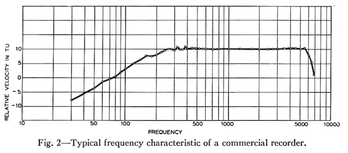
source: “Recent Advances in Wax Recording”, Halsey A. Frederick, Bell System Technical Journal, Vol.8, Issue 1, pp 159-172 (January 1929)
archived at Internet Archive (archive.org)
縦軸は relative velocity なので、定速度特性のピックアップで再生した際の周波数特性グラフと同じになるということ
まさにこの上図に示された特性で記録していたということですが、では、この特性(250Hz ベースターンオーバー、4,500Hz または 5,500Hz から急速減衰)を実現するために、当時はどのような方法をとっていたのか。
The frequency characteristics of the recorder was just as shown in the above figure – so how did the recording chain of these early years accomplish this characteristics (250Hz bass turnover, and above 4,500Hz or 5,500Hz constant acceleration)?
のちに技術が進歩するに従い、上図のようなカッターヘッドの記録特性を実現するために、カッターヘッドの裸特性に加え、下図 (A) のような RC回路(R = resistance, 抵抗)(C = capacitance, コンデンサ)や LRC回路(L = inductor, コイル, Lenz に由来)という電気回路を使ったイコライザ(補正装置)、そして後述するフィードバック回路などが使われますが、Western Electric / Bell Labs が世界で初めて電気録音を実現した1925年〜1927年当時は、違う方法がとられていました。
As the time went by, such compensator circuits (RC circuits: R = resistance; C = capacitance, or LRC cirucuits: L = inductor, derived from Lenz), as well as “feedback” circuits (which I will mention on the coming articles) were used along upon the cutterhead’s uncompencated frequency characteristics, in order to accomplish the target recording characteristics. However, in 1925-1927 when the world’s first electric recording machine was produced, a different approach was used.
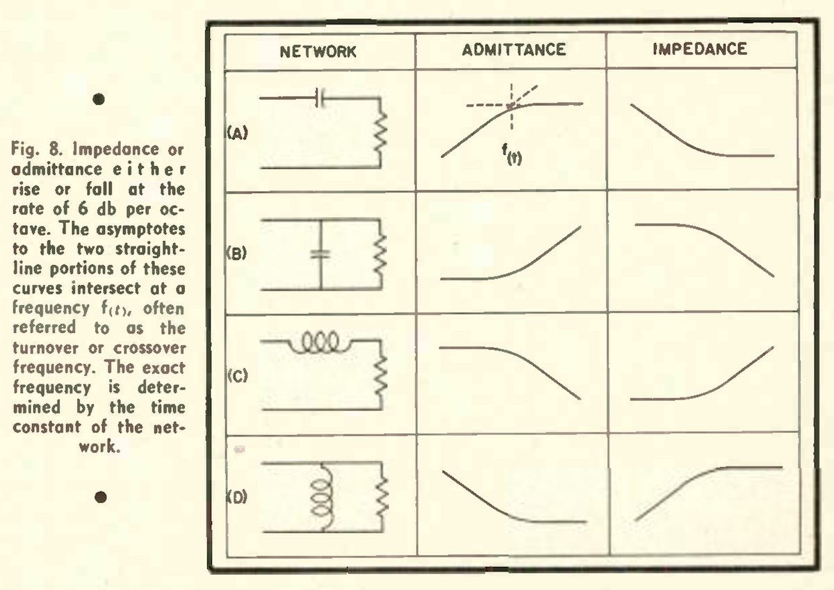
source: “Evolution of a Recording Curve”, R.C. Moyer, Audio Engineering Magazine July 1953, pp. 19-22 & 53-54, World Radio History website (1953)
RCA Victor の R.C. Moyer 氏による、 Audio Engineering 誌 1953年7月号に掲載された、RIAAカーブについての解説記事より。
この図自体は、再生時のフォノイコライザの実現方法の説明に出てくるものです。
Please note this figure itself appeared in the RIAA playback compensation circuits.
のちに「ラバーラインレコーダ」(rubber line recorder) と呼ばれることになる当時の録音システムでは、筒状のラバーが装着されていました。このラバーラインのダンピング特性や、カッターヘッドの構成部品の特性によって、250Hz 以上 4,500Hz〜5,500Hz 辺りまでのカッターヘッドの特性を「定速度特性」的にフラットにし、さらにラバーラインに加えて専用のアンプの出力に合わせたコイルにより 250Hz 以下の「ほぼ定振幅特性」が担保されていたのです。
The recording system – which was later called “rubber-line recorder”, had a long rubber line to dump the resonance. The rubber-line characteristics (along with other characteristics of recording head parts) controlled the “constant-velocity” characteristics between 250Hz and 4,500Hz (or 5,500Hz). Also, by matching the audio coils to the output of the cutting amplifier, approximately “consant-amplitude” characteristics below 250Hz was maintained.
つまり、信号の入力から、カッターヘッドののアーマチュアとスタイラスまでに至る、各部品のあらゆる物理的・電気的特性を使って、総合的にコントロールしていたのです。
In other words, by synthesizing every mechanical / electical characteristics of all the parts and components (including that of cutterhead’s armature and styli) in the recording chain, the frequency response was totally controlled.
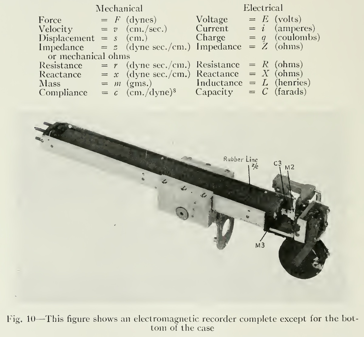
source: “Methods of High Quality Recording and Reproducing of Music and Speech Based on Telephone Research”, by J.P. Maxfield and H.C. Harrison, Bell System Technical Journal Vol.5, p.493-523, 1926
このラバーラインを含め、さまざまな部品の物性を駆使し、カッターヘッドの共振周波数を手なづけ、目標とする記録周波数特性を制御していました
Engineers managed to control the final recording characteristics with several physical properties including this rubber line.
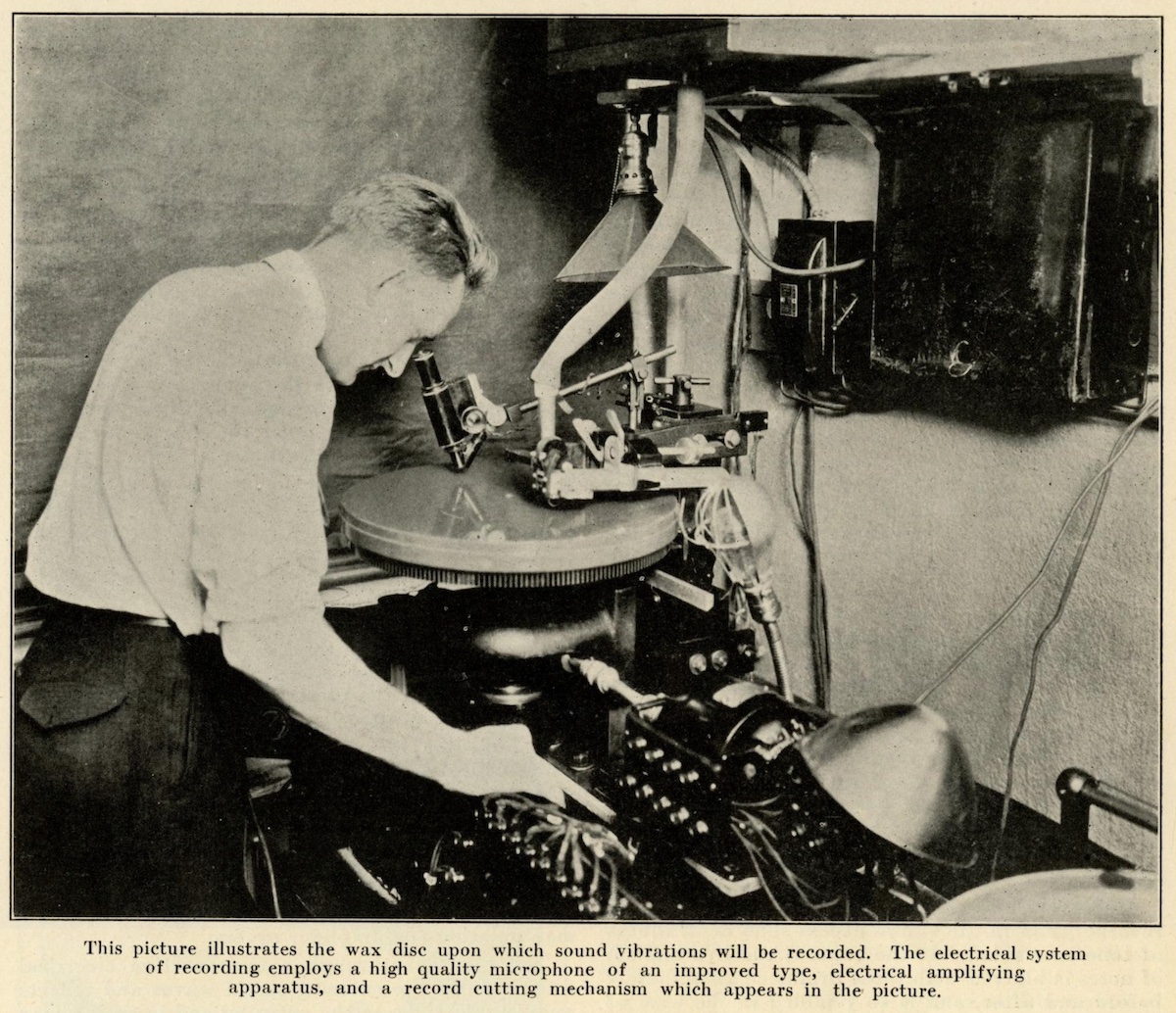
source: “How the Sounds Get Into Your Record by the Electrical Process”, The Phonograph Monthly Review, Vol.1, No.1, p.5, Oct. 1926
Western Electric エンジニアによって書かれた記事中に登場する、電気録音中の George Groves 氏の写真
The picture illustrating the wax disc recording by George Groves. This photo appeared in the article written by Western Electric engineers.
ここで、ラバーラインレコーダについて触れている文章を2つ引用します。1つは1946年のベルラボの記事、もう1つは2003年AES大会での研究発表資料です。
Below I’m quoting two articles regarding the rubber line recorder – one is from Bell Labs, 1946, and the other is from AES Convention Paper, 2003.
…H.C. Harrison developed a recorder (Patents 1,678,116 and 1,663,884) in which the armature, the cutting stylus, the connecting shaft sections, and a rubber transmission line were combined as elements of an electromechanical network.
… H.C. Harrison 氏が開発した録音機器(特許番号 1,678,116 および 1,663,884)は、アーマチュア、カッティング針、接続シャフト、ラバー伝送ラインが、電気機械ネットワークの構成部品として接続されている。
He was able to use electrical transmission theory as a basis for this recorder because he recognized that in mechanical transmission systems, masses are analogous to electrical inductances as elements for storing kinetic energy. Similarly, compliances are analogous to capacitances as elements for storing potential energy. Mechanical resistance was provided by using a soft rubber rod in torsion. Such a rubber rod is a high-loss transmission line, and hence can be used as a mechanical resistance. At the armature, which is the coupling point between the electrical and mechanical transmission systems, the impedances of the two systems were matched.
機械的伝送システムにおける質量が、運動エネルギーを蓄積するという点で電気回路におけるインダクタンスに相当し、同様にコンプライアンスは位置エネルギーを蓄積するという点でキャパシタンスに相当する、と氏は認識していた。だからこそ、氏は録音機器の理論的基礎として電気伝達理論を用いることができた。機械的な抵抗は、ねじり振動を伝える柔らかいラバーラインを使うことで得られるが、このラバーラインは高損失伝送システムであるので、機械的抵抗として利用可能であった。電気的伝送システムと機械的伝送システムの界面であるアーマチュアでは、両システムのインピーダンスが一致されるようになっていた。
Historic Firsts: The Orthophonic Phonograph, Bell Laboratories Record 24, pp.300-301 (August. 1946)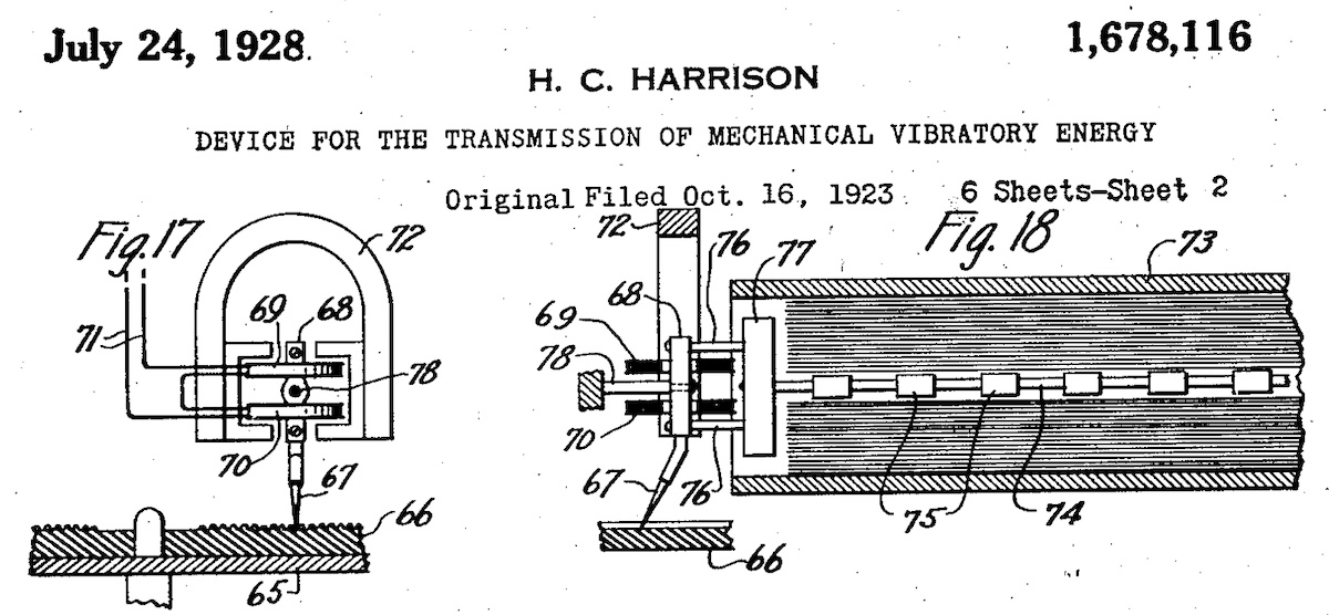
source: “Device for the transmission of mechanical vibratory energy“, US Patent 1,678,116A, 1928
特許資料に登場する、ラバーラインとカッターヘッドの図版
Illustrations of “rubber-line” and electromagnetic cutter head, as shown in the Harrison’s patent document
The principle innovation in the cutterhead was the termination of the armature system by a long rubber line, made of concentric tubes. This performed as a mechanical equivalent of the transmission line filter familiar to telephone engineering. By terminating the moving system impedance correctly no energy is reflected from the rubber line.
このカッターヘッドの革新性は、アーマチュアシステムの終端を同心円筒状に作られた長いラバーラインで終端したことである。このラバーラインは、電話工学でお馴染みの伝送経路フィルタと機械的に等価とみなせる。可動システムのインピーダンスを正しく終端することにより、ラバーラインからのエネルギー反射が発生しなくなる。
(…snip…) The cutter had a constant velocity response from 200Hz to 4kHz after which it became constant acceleration to about 6kHz.
(中略) カッターは200Hzより4kHzまで定速度に応答し、その上の帯域では6kHzまで等加速度に応答する特性を備えた。
By suitable matching of the audio coils to the output of the cutting amplifier a first order curve was obtained below 200 Hz.
そしてカッティングアンプの出力にコイルを適切にマッチさせることで、200Hz以下では1次曲線(直線)を得ることができた。
“The Development of Disc Cutting Heads”, Sean Davies, AES Convention Paper 5751 (2003)また、当時の Western Electric カッターヘッドの裸特性における共振周波数は1925年の初代、1927年の改良版ともに 1,000Hzだったそうです(出展: “Methods of High Quality Recording and Reproducing of Music and Speech Based on Telephone Research”, by J.P. Maxfield and H.C. Harrison, Bell System Technical Journal Vol.5, pp.493-523, 1926)。
What’s more, the original Western Electric cutterhead (1925) and the upgraded version (1927) had singly resonant peak at 1,000Hz (uncompensated) (source: “Methods of High Quality Recording and Reproducing of Music and Speech Based on Telephone Research”, by J.P. Maxfield and H.C. Harrison, Bell System Technical Journal Vol.5, pp.493-523, 1926).
これを電気回路でいうバンドパスフィルタと等価な機械的回路の特性を使い、初代では 4,500Hz に、アーマチュアのピボットを見直しコンプライアンスを絞り込んだ改良版では 5,500Hz にもっていきました。(出典: “Manual of Analogue Sound Restoration Techniques (Copeland, 2008)”, p.120)
And the original version of the WE cutterhead had primary resonance at 4,500Hz using a band pass type of (mechanical) circuit. Then the upgraded version at 5,500Hz by redesigning the means of pivoting the armature, and tightning up the compliance.(source: “Manual of Analogue Sound Restoration Techniques (Copeland, 2008)”, p.120)
1.2.1 Recording Curve by Electromechanics / 電気機械じかけの録音カーブ
下の「Fig. 7. Responses of Western Electric 1A and 1B cutters.」という図の点線部分が、そのラバーが新品の時の特性を表しているそうです。しかし、ラバーラインが劣化し、図の実線部分のように160Hzあたりに山ができた特性になってしまっても、全てのレコードレーベルがすぐに新品に交換できたわけではなかったそうです。また、気温や湿度によっても特性が変わりやすかったそうです。そのため、当時のレコードの中には、理想的なカーブで記録されていないものも少なくないそうです。
この辺りの話は References で触れた “Manual of Analogue Sound Restoration Techniques” (Copeland, 2008) の他、“The Gramphone Record” (H.C. Bryson, 1935) などで詳しく解説されています。
According to the explanation in the “Manual of Analogue Sound Restoration Techniques” (Copeland, 2008), the dotted line of the below “Fig. 7. Responses of Western Electric 1A and 1B cutters” shows the response of the cutter “when the rubber line was new”. Also, another description can be also found: “Top professional recording companies were able to afford new spare parts, but by about 1929 there was rather a lot of ill-understood tweaking going on in some places” – that means, not all the recordings by many manufacturers (that used the new electrical recording system) didn’t have an ideal recording characteristics due to the aged/perished rubber line. Other reference (“The Gramophone Record”, by H.C. Bryson, 1935) notes the rubber line was very sensitive and affected by climate changes.
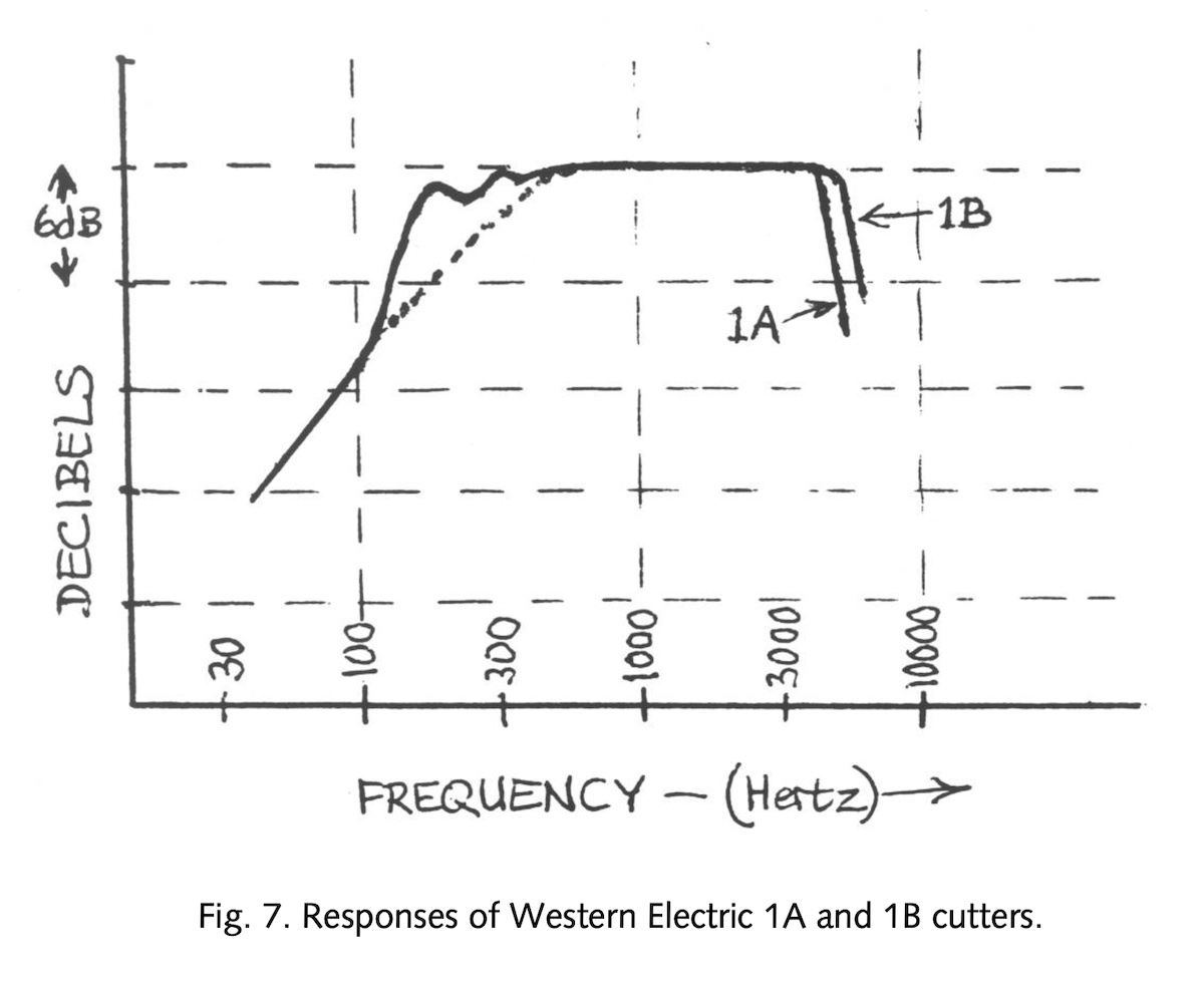
source: “Manual of Analogue Sound Restoration Techniques”, p.120, by Peter Copeland, The British Library (2008)
別の書籍でのグラフ。ここで1Aと書かれているのは1925年のオリジナルカッターヘッド、1Bが1927年のカッターヘッドの特性とのこと(正式名ではない)。
グラフ点線部分は、ラバーラインが新品の時の理想の特性
Please note in this graph “1A” is the original cutterhead (1925) and “1B” being the improved cutterhead (1927) – these names were not officially used.
つまり、21世紀を生きる我々が、再生機器側で「ターンオーバー」「ロールオフ」のつまみを切り替えることにより多様な再生カーブを簡便に変更できる時代とは違い、ラバー部品など様々な物理特性も使って録音カーブをコントロールしていたのです。
So, unlike we fine-tune the playback EQ curve by rotating “turnover” and “rolloff” knobs on the reproducing component(s) very easily, recording instruments (of nearly 100 years ago) obtained the recording curve by utilizing various electromechanical characteristics, including the legendary rubber line.
いや、そもそも、いまでいうところの「EQカーブ」なんて概念もなかった時代だったわけですよね。ただただ、記録可能な周波数帯域をより広げ、それをディスクの溝に正確に効率的に記録する、という技術革新(そして特許レース)の、いちばん最初のスタート地点。
Or we can say, even the concept of “recording curve” and “reproduction curve” was not born yet. Inventors / researchers / engineers were at the very start of the “innovation” – and many mechanical, electronic and technical challenges – (and the race for patents) – in order to record wider frequency range into a long spiral groove on the master wax/lacquer more precisely.
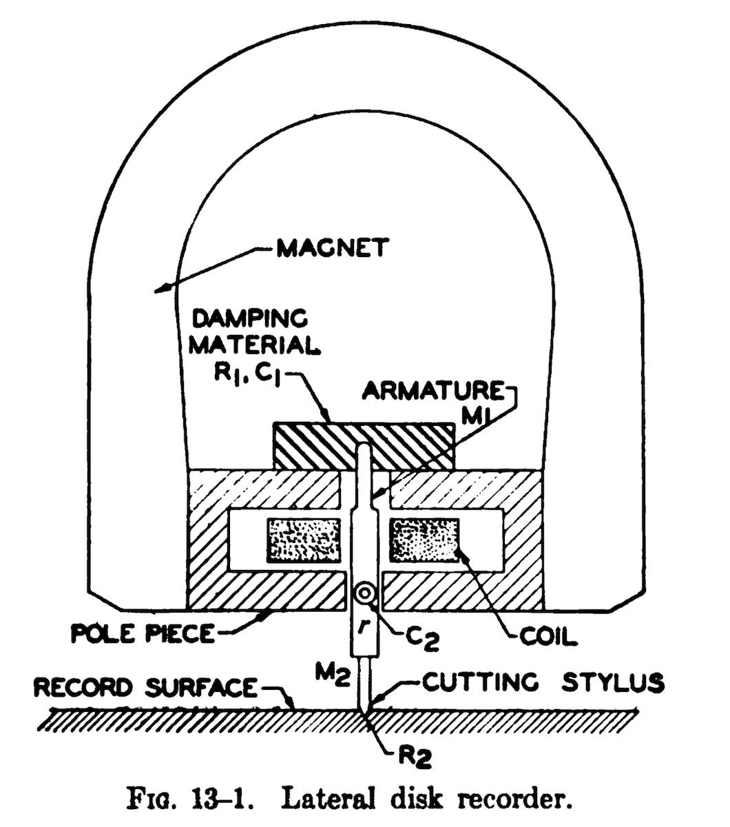
source: “Elements of Sound Recording”, p.227, by John G. Frayne and Halley Wolfe, 1949.
典型的なマグネットカッターヘッド (MI型) の簡略図
1.2.2 Playback Compensation by Acoustics / アコースティックによる再生補正
さらに、再生側も、当時は電気回路で補正するのではなく、アコースティックで周波数帯域を補正していました。世に名高い名機、Victor Talking Machine 社の ヴィクトローラ・クレデンザ の巧妙に折り畳まれたロガリズミックホーンで低域増幅を行い、結果として115Hz〜5,000Hzあたりでほぼフラットの再生を実現していたということになります。
Furthermore, in these very early days, reproducing frequency compensation was not by electrical circuit – it was accomplied acoustically. The ingeniously folded-back-on-itself logarithmic horn of a highly acclaimed Victrola 8-30 Credenza of Victor Talking Machine Co., extends the bass frequency range, resulting a nearly flat response from 115Hz to about 5,000Hz.
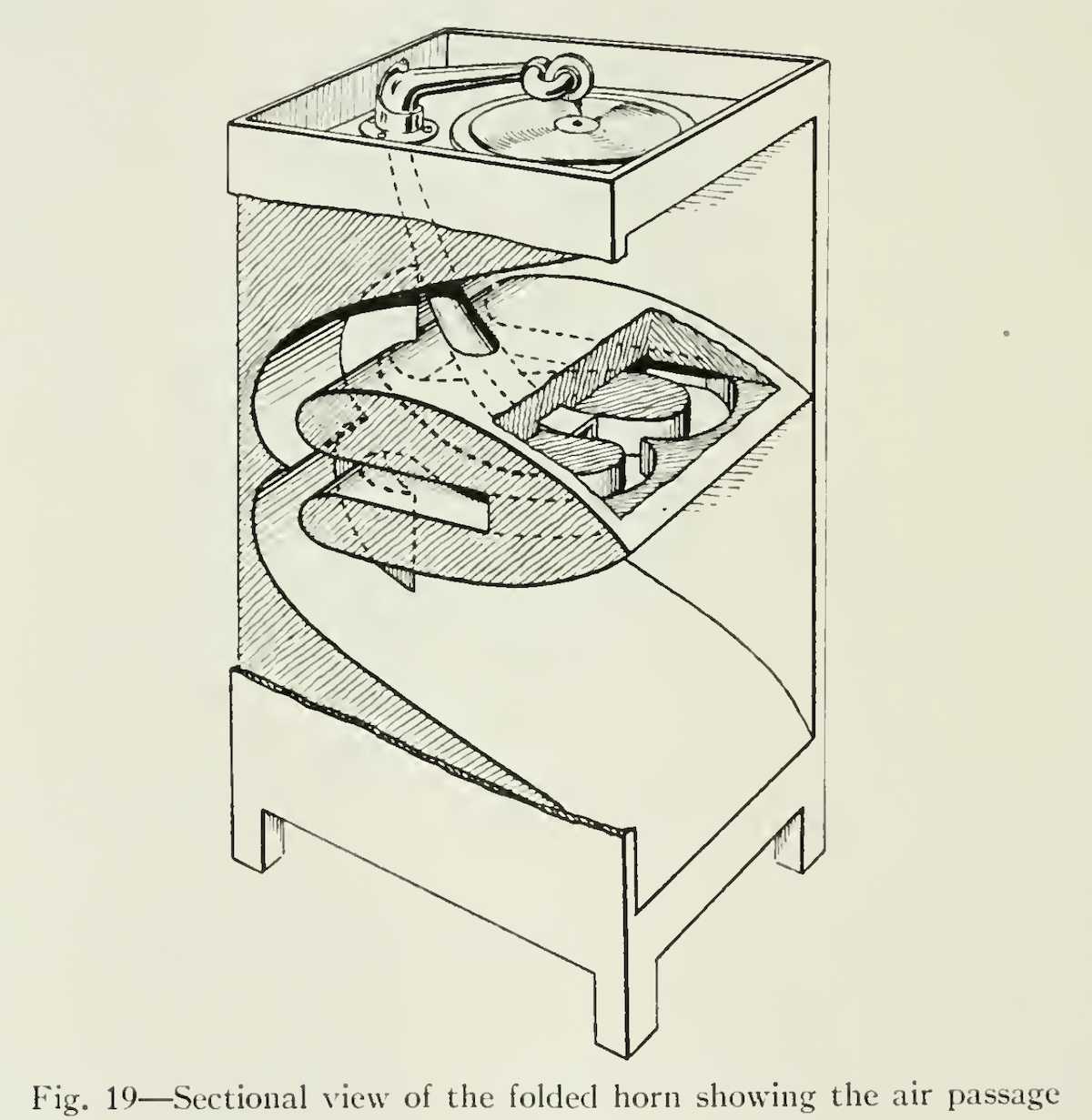
source: “Methods of High Quality Recording and Reproducing of Music and Speech Based on Telephone Research”, by J.P. Maxfield and H.C. Harrison, Bell System Technical Journal Vol.5, pp.493-523, 1926
おそらくVictor Orthophonic Victrola 8-30 Credenza と思われる再生機器の断面図。この見事な構造により、低域補正をしてフラット再生したわけです。
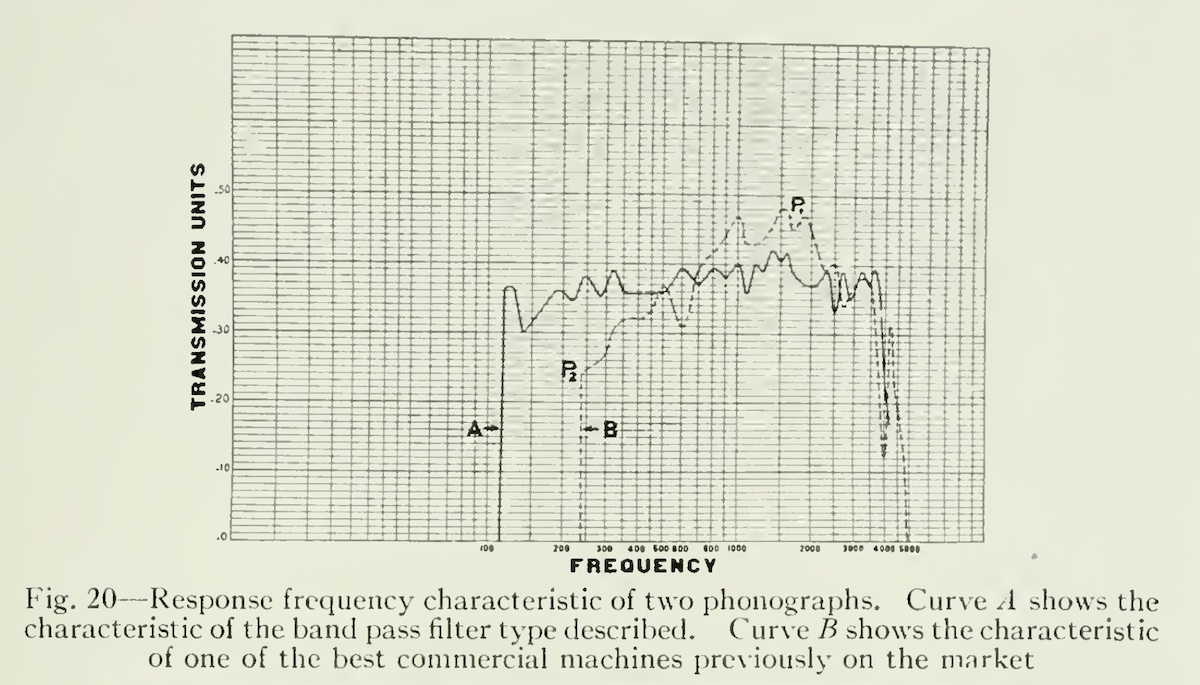
source: “Methods of High Quality Recording and Reproducing of Music and Speech Based on Telephone Research”, by J.P. Maxfield and H.C. Harrison, Bell System Technical Journal Vol.5, pp.493-523, 1926
この周波数特性グラフのAが、当時の電気録音ディスクを Credenza で再生した際の特性ということになります。
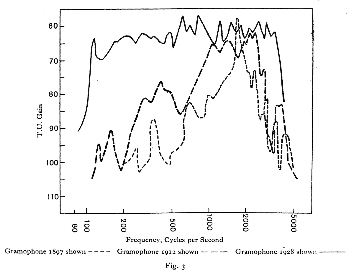
source: “Progress in the Recording and Reproduction of Sound”, A. Whitaker, pp.35-41, Journal of Scientific Instruments, Vol. 5, 1928.
1897年と1912年のアコースティック蓄音機、1928年の電蓄の再生周波数特性を比較したグラフ
これら当時としての最高技術をもってしても、100Hz〜5,000Hz 程度のフラット再生が限界だった時代です。それでも、現代につながる100年近く前の革新的な発明の素晴らしさは色褪せませんし、当時クレデンザで電気録音レコードを聴くことが出来たひとにぎりの恵まれた方々は、アコースティック録音時代と比べてその素晴らしい音質に驚愕したことでしょう。
These technique and implementation, although they were “the best technology around that time”, provided only limited flat response of narrow range like 100Hz to 5,000Hz at most. However, it was truly a invention and innovation of nearly a century ago, and it was the very start of the electrical recording/reproduction technology that we appreciate every day in the 21st century. People of 100 years ago – who luckly had a chance to listen to the sound of the electrically recorded disks with the Victrola Credenza – would be surprised and asnotished with the innovative sound improvement.
とはいえ、電気回路によるアンプやイコライザがレコード再生用に用意されていなかった、アコースティックな再生装置しかなかったタイミングですので、再生機器が異なれば、再生音の周波数特性も異なります。あくまで「当時としては」「レコードの溝に最大限の情報を詰め込むことに成功した」「ただしその品質を最大限享受するには、特定のしかも最高級の装置が必要」というものだったわけですね。
On the other hand, it was such a timing when such reproducing equipments as electric amplifiers / equalizers were not yet available – there were only acoustical instruments for reproduction: different hand-wound phonograph players reproduces sound with different frequency response. So, when we look back the innovation of the electrical recording from the 21st century, we can say that it enabled “to record the maximum info (for that time) of the sound on the groove”, but “you needed a specific hi-end playback environment (like Victrola Credenza) to assimilate the highest sound quality”.
1.4 The summary of what I got so far / 自分なりのまとめ
予想以上に長くなってしまいましたが(笑)、ベースターンオーバー周波数を境に、下は定振幅、上は定速度、という記録方法が誕生したところまで書きました。先述の Galo 氏の論文のイラストで言うと、以下のようになります。
Well, in this Part 1 article (that became a way longer than I initially intended…), I have learned the very first recording curve for electrical recording – constant amplitude (below the turnover frequency) and constant velocity (above the turnover frequency). Below is the illustration from the famous G.A. Galo’s article.
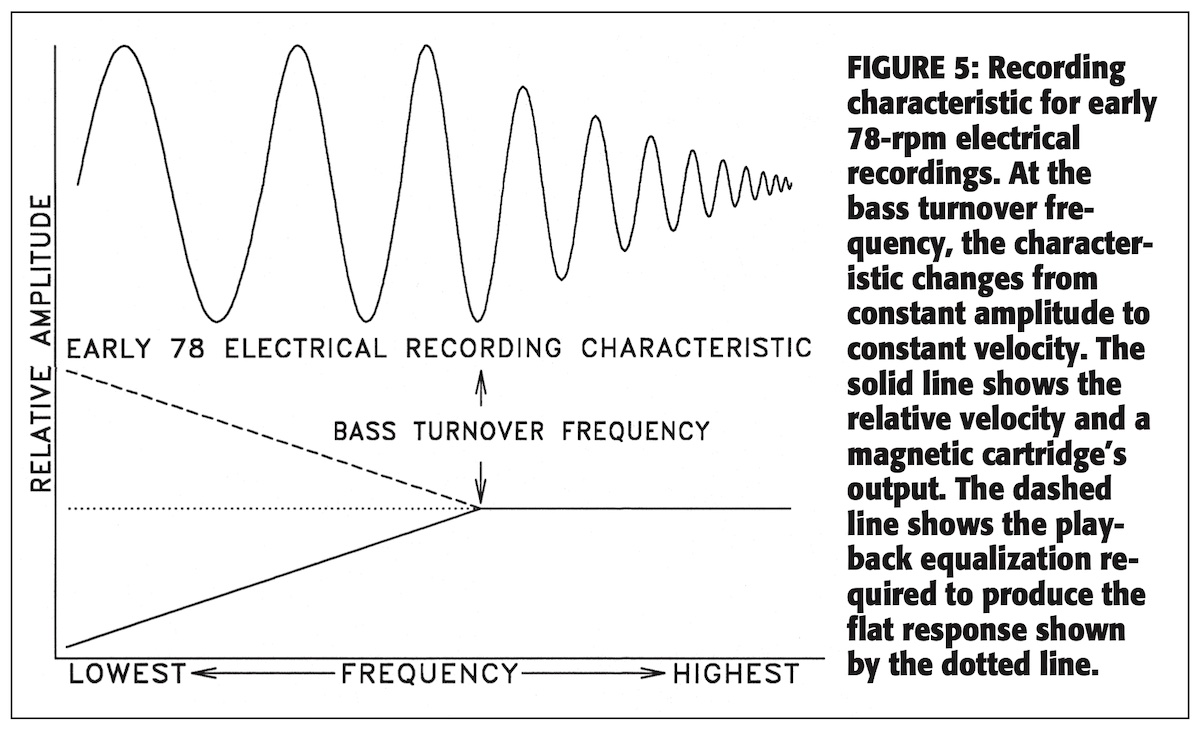
source: “Disc Recording Equalization Demystified”, The LP Is Back!, p.45-54, audio express website (1999)
ベースターンオーバー周波数(およそ250Hz、時定数636μs)を境に、定振幅+定加速を合体させた、電気録音最初期の録音カーブ
ターンオーバーより下の周波数における点線部分(増幅)が、再生カーブに相当する
残念ながら、私は電気機械工学・電子工学の専門家ではないため、各種論文を読んでも100%の理解が出来ない難しい部分もありますが(笑)、ともあれいい勉強になりました。
Unfortunately, I am not an expert in Electrical Engineering / Electromechanical Engineering, so I don’t think I can fully understand the whole contents of many research papers and articles, but anyway I enjoyed the relearning a lot.
さてさて、ここまでの内容をざっくりまとめると、こんな感じでしょうか。
…so, the rough summary of my understanding so far would be something like this:
レコードに音溝を記録する際、基本的には定速度特性で記録される
When a sound groove is cut on the record master, basically it has a constant-velocity characteristics.
全周波数帯域を定速度特性で記録すると、低域では溝が横に広がりすぎ、片面に記録可能な時間が短くなってしまう。また、高域では溝の振幅が小さくなりすぎ、サーフェスノイズに埋もれてしまう。
If the constant-velocity recording is applied to all the frequency range, two issues arrise: in low frequency range, groove excursion becomes much wider, resulting a short playing time for each side of a record; in high frequency range, the amplitude is too low to cope with surface noise.
そこで世界初の電気録音において、250Hzあたりから下は定振幅特性で、それより上は定速度特性で記録された。切り替わり周波数をベースターンオーバー周波数と言う。
When the first electrical recording was invented, ranges below around 250Hz had constant-amplitude characteristics, and for above around 250Hz constant-velocity charactieristic. The point where the transition from constant amplitude to constant velocity is called bass turnover frequency.
電気録音最初期においては、記録可能な高域上限はせいぜい4,500Hz〜5,500Hzであったため、当時はそれ以上の帯域はサーフェスノイズに対抗するためもあって急速減衰(定加速度特性)で記録された。そもそも、当時のスピーカでは高域まで再生できなかった。
In the early electrical recording days, the highest possible frequency that could be recorded was 4,500Hz to 5,500Hz at most, so the higher range was rapidly attenuated with constant-acceleration characteristics to cope with surface noise. Also, loudspeakers in this era could not reproduce higher frequencies in the first place.
これら録音記録特性は、現代のように電気回路で実現するのではなく、当時は各種構成部品の物性を活用して実現された。Bell Labs / Western Electric の最初の電気録音発明者である Maxfield & Harrison によって、電気回路のシステムと等価な機械システムを構成するアナロジーが確立され、のちのスピーカ技術発展にも貢献した。
These recording characteristics was accomplished by fully utilizing physical properties of all the elements and parts of the recording equipment, unlike recent decades when the recording curve is fully controlled by a dedicated electrical circuits. Maxfield & Harrison, inventors of Bell Labs / Western Electric’s first electrical recording system, made of the analogies between the electrical and the mechanical systems, that later contributed the evolution of loudspeakers as well.
電気録音誕生当時の再生はアコースティック機器で行われ、低域増幅(いまでいう再生カーブ)はロガリズミックホーンを用いて行われた。
When the electrical recording was born in 1925, the playback compensation (that is similar to what we now call “playback curve”) was done with logarithmic horn of the acoustic player.
次回は引き続き歴史を辿り、世界初の電気録音音源、世界初の電蓄(電気再生プレーヤ)、ラジオ業界との関係について学んでいきます。
My next post will feature the continuing history, including world’s first electrical recordings, world’s first electrical reproducing system, and the relationship with radio industry.
» 続き / Sequel: “Things I learned on Phono EQ curves, Pt.2” »
