Phono EQ Curves に関する筆者の学習過程を、これまで Pt.0〜Pt.25 として連載してきました。本シリーズ Phono EQ Curves Liner Notes は、その続編ではなく、別の角度からのアプローチです。LP のジャケット裏に書かれた解説 (ライナーノーツ) のように、本編とは別の物語を、別の温度感で記録するためのシリーズです。
For the past few years, I have been documenting my own learning around phono EQ curves in the long-running series Pt.0–Pt.25. This new series, Phono EQ Curves Liner Notes, is not a continuation of that body of work but rather a different approach altogether. Like the liner notes printed on the back of an LP jacket (separate from the music itself, written in a different register), these pieces are meant to record stories and findings that sit alongside, rather than inside, the main series.
第 1 弾 Liner Notes I は、Nicholas Bergh さんのご厚意で提供を受けた、RCA Victor 社内エンジニアリングノートの 1955年4月18日付のページについての発見報告です。
The first installment, Liner Notes I, is a report on a discovery: a single page from an internal RCA Victor engineering notebook dated April 18, 1955, generously shared with me by Nicholas Bergh.

source: RCA Victor Engineering Book, Notebook No.1, page 6, dated 4-18-55
photo courtesy of Nicholas Bergh
RCA Victor 社内エンジニアリングノート 1, p.6 (1955-04-18)。Nicholas Bergh さん提供
Contents / 目次
- 変更履歴 / Revision History
- I.1 Opening the Liner Notes Series
- I.2 An Encounter with the Source
- I.3 The Page Itself — Notebook 1, p.6
- I.4 OLD and NEW — What Changed
- I.5 Twenty-Two Rows, Within ±0.1 dB
- I.6 Not “First Alignment,” but “Refinement”
- I.7 What This Page Tells Us, What It Leaves Open
- I.8 Acknowledgements
- I.9 Related Links
変更履歴 / Revision History
- 2026年5月13日: 初版公開
- May 13, 2026: Initial publication
本シリーズ Phono EQ Curves Liner Notes は、これまでの連載「Things I learned on Phono EQ Curves Pt.0〜Pt.25」 の補完シリーズです (連載続編ではなく、別シリーズとして位置付けます)。詳しくは 連載の読み方ガイド をご覧ください。
This series, Phono EQ Curves Liner Notes, is a companion to the existing series “Things I learned on Phono EQ Curves Pt.0–Pt.25” (positioned as a separate series rather than a continuation of it). For details, please see the guide to reading the series.
本稿は、筆者自身の学習・調査過程を記したものです。間違いの指摘や異論は遠慮なくお寄せください。
This piece is a record of the author’s own learning and inquiry. Corrections and disagreements are most welcome.
I.1 Opening the Liner Notes Series
もともとは、Pt.0〜Pt.25 の続編として「Pt.26」 を書くつもりでした。けれども、Pt.24 でいったん区切りをつけ、全体のまとめとして Pt.25 を書いたあのシリーズは、すでに一区切りがついた感覚があります。ふたたび「Pt.X」 のナンバーを継ぎ足すよりも、別のかたちや温度感で、これからの発見やノートを記していきたい。そう思って立ち上げたのが、本シリーズ Phono EQ Curves Liner Notes です。
At first, I’d thought I would write a “Pt.26” as the next installment of Pt.0–Pt.25. But Pt.24 already felt like a natural pause, and Pt.25, written as a wider overview, gave the series a sense of having reached a natural close. Rather than continuing to add “Pt.X” numbers, I wanted to start writing in a different shape, at a different temperature, recording whatever new findings and notes still emerge over time. That impulse became this series, Phono EQ Curves Liner Notes.
シリーズ名は、LP のジャケット裏に書かれた解説 (ライナーノーツ) からとりました。アルバム本編が音楽そのものであるなら、ジャケット裏のライナーノーツは、その音楽が録音されるまでの物語、音楽家の生きた時代、エンジニアの工夫といった、本編からは聞こえてこない背景を綴った、独立した文章でした。Pt.0〜Pt.25 が私にとっての「学習履歴」「研究ノート」 だったとすれば、本 Liner Notes シリーズは、本編に含めきれなかった物語や発見、あるいは Pt.25 以降に明らかになった知見を、しずかに書き留めていくための場としたいと思います。
The name comes from the liner notes printed on the back of an LP jacket. If the album itself is the music, the liner notes are the surrounding stories — the road that led to the recording, the world the musicians lived in, the engineers’ craft — written as their own small, independent text, not as part of the music. If Pt.0–Pt.25 has been my “learning record” or “research notebook,” then this Liner Notes series is meant to be a quieter place: somewhere to set down the stories and findings that didn’t fit inside the main body, along with things that have come to light since Pt.25.
本シリーズは Liner Notes I, II, III … と続編を重ねていく想定です。第 1 弾の本稿 Liner Notes I では、Nicholas Bergh さんからご厚意で提供を受けた、RCA Victor 社内エンジニアリングノートの 1955年4月18日付のページについての発見報告を中心に、その史料との出会いの物語と、私なりの読み解きとを併記してお届けします。
I’m imagining this as a series — Liner Notes I, II, III, and so on. For this first installment, Liner Notes I, the centerpiece is a single page from an internal RCA Victor engineering notebook, dated April 18, 1955, generously shared by Nicholas Bergh: a report on the finding itself, set alongside the story of how I came to encounter the source, and my own reading of what is on the page.
I.2 An Encounter with the Source
Nicholas Bergh さんについては、本シリーズ本編の Pt.3 セクション 3.1 ですでに少しだけ書きました。2022年秋頃、Pt.0〜Pt.3 を執筆していた頃にメールでのやりとりがはじまり、それから 4年弱、断続的に対話が続いてきました。
I have previously written briefly about Nicholas Bergh in the main series, at Pt.3 §3.1. Our email correspondence began in the fall of 2022, around the time I was writing Pt.0–Pt.3, and has continued, intermittently, for nearly four years since.
やりとりは、こちらの問いばかりが流れていく一方通行ではなく、ときどき逆向きにもありました。Nick さんから戦前日本の映画撮影・録音機材、特に 1930年代に日本の松竹スタジオで使われていた土橋式トーキー機材について教えてほしいと頼まれたこともありましたし、リコー マイティーチャー (サウンドシート) について調べてもらえないかと相談を受けたこともありました。それと並行して、私からはディスク録音史にまつわる細かな質問を、必要なときに必要なだけ送り、丁寧な返信をいただいてきました。
The exchanges were never just a one-way flow of questions from my side; the direction sometimes ran the other way too. Nick once asked me about pre-war Japanese motion-picture and recording equipment — specifically the Tsuchihashi-shiki talkie sound equipment used at the Shochiku studios during the 1930s. On another occasion, he asked whether I could look into the Ricoh Sound Sheet (also known as the Ricoh Syncrofax sheet), a Japanese brand of flexi disc. In parallel, I sent him granular questions about disc recording history whenever I needed to, and always received careful, generous replies.
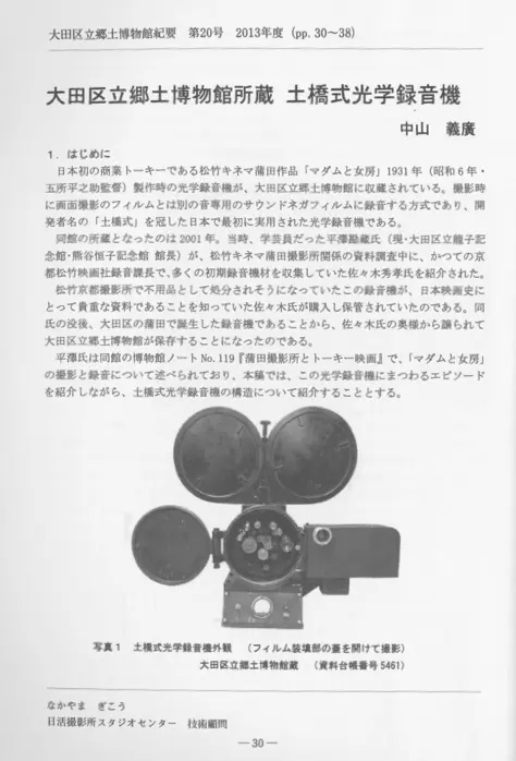
source: Nakayama Yoshihiro, “Tsuchihashi-shiki Optical Recording System Held by the Ota City Folk Museum,” Bulletin of the Ota City Folk Museum, Vol.20 (2013), pp.30-38, opening page
出典: 中山 義廣「大田区立郷土博物館所蔵 土橋式光学録音機」 大田区立郷土博物館紀要 Vol.20 (2013), pp.30-38、冒頭ページ
2022年5月の ARSC オンラインカンファレンスで Nick さんが発表された「Understanding Errors in Archival Phono EQ Standards by Looking at Original Disc Recording Equipment」 についても、視聴後にいくつか質問させてもらったことがあります。やりとりの過程では、Nick さんが個人で所蔵されている Fairchild 641 System や Cinema Engineering 7087 Playback EQ といった、実物にはなかなかお目にかかれない貴重な録音再生機器の写真を、惜しみなく提供していただきました。さらには、Nick さんが関わった音源復刻、たとえば映画『Becoming Led Zeppelin』 の裏話まで聞かせてもらったこともあります。
I had also followed up with a few questions after watching Nick’s presentation at the ARSC online conference in May 2022, “Understanding Errors in Archival Phono EQ Standards by Looking at Original Disc Recording Equipment.” Through the years of correspondence, Nick has generously shared photographs of his own holdings — the Fairchild 641 System, the Cinema Engineering 7087 Playback EQ, and other historic recording and playback machines that one rarely gets to see in the flesh. He has even shared behind-the-scenes stories from restoration work he was involved in, including the audio restoration for the film Becoming Led Zeppelin.
そんな対話が幾度となく重なってきたなか、ちょうど FAQ 記事「規格文書の時定数表記は LCR から RC にいつ書き換わったのか?」を執筆中、1954年1月の RIAA Bulletin E1 のオリジナル文書 (またはその直接の手控え) についての話題になりました。この文書の現物はいまだに確認できずにいるものです。それについてのメールのやりとりが続くなか、話題は自然と、先の ARSC 2022 プレゼンで Nick さんが一瞬スライドに映していた、1957年 RCA の LCR 録音 EQ (McLaughlin の手描き図) の話に移っていきました。そして Nick さんから、これに対応するシミュレーションを試してみたことはあるか、と私に問いかけがあったのです。
Across these many small exchanges, while I was writing the FAQ entry “When did the standards documents change their wording from LCR to all-RC?,” the conversation turned to the original of RIAA Bulletin E1 from January 1954 (or any direct desk copy of it). The document itself remains, to this day, something I have not been able to lay my hands on. As we continued exchanging emails about it, the topic drifted naturally toward something Nick had flashed briefly on a slide during his ARSC 2022 talk: McLaughlin’s hand-drawn schematic of the 1957 RCA LCR recording EQ. At that point, Nick asked me whether I had ever tried running a simulation of that circuit.
そして、その問いへの答えを準備しているのと並行して、Nick さんは Bulletin E1 を探した結果として、いくつかの関連史料の写真を一括で送ってくださっていました。Bulletin E1 そのものは Nick さんの手元にもなかったとのことでしたが、それに「最も近いだろうもの」 として、本稿の主役となる RCA Engineering Notebook 1 のあるページの写真、Notebook 1 の INDEX 3 ページ (収録範囲が 1955年3月11日から 1960年1月4日にわたることが分かりました)、ある手書きの “RECORDING CHARACTERISTIC RIAA” graph (Date unknown ながら、紙質や文字の感じから相当古いと見え、Bulletin E1 (1954) 相当の手控えの 1 枚である可能性も残ります)、それと 1949年の NAB recording standard などが、計 6 枚として届いたのでした。
Meanwhile, as I was preparing to take up that question, Nick had already pulled together — in response to my Bulletin E1 inquiry — a set of photographs from his own paperwork, and sent them over in a single batch. Bulletin E1 itself was not in his hands either, he told me, but as the “closest things to it” that he had on file, the batch contained: a photograph of the very page from the RCA Engineering Notebook that would later become the central page of this article; the three-page INDEX of Notebook 1 (from which it became clear that the notebook itself covers the period from March 11, 1955, through January 4, 1960); a hand-drawn graph labeled “RECORDING CHARACTERISTIC RIAA” (date unknown, but evidently quite old, judging from the paper and the handwriting — possibly one of the desk-copy sheets attached to Bulletin E1 in 1954); and the 1949 NAB recording standard. Six photographs in all.
こうしてはじまったのが、本サイトの新しい FAQ「カッティング EQ を完全に打ち消す再生 EQ はあるのか?」 の作業でした。そんな中、Nick さんからさらにもう 1 通、メールが届きます。先ほどの一括送付のなかで本稿の主役となる 1 ページの写真も含まれていたのですが、その後改めて、Doug Pomeroy さんから引き継いで Nick さんが保管していた原本を高解像でスキャンし直し、別送してくださったのです。本稿の主役となる、まさにそのページです。
This is how the work began on a new FAQ entry, “Can a Playback EQ Perfectly Cancel a Cutting EQ?“. And then, while I was deep in that work, another email from Nick arrived. The earlier batch had already included one photograph of the centerpiece page; but he had now gone back to the original notebook itself — the one he had inherited from Doug Pomeroy — and rescanned that single page at far higher resolution. That second, higher-resolution image is the one I have been working from in this piece: the page that stands at the heart of everything that follows.
そのページから読み取ったいくつかの数字、そして私なりに進めていたシミュレーションの結果が突き合わさったとき、1955年4月18日というその日、RCA Victor 社内のラボで何が確認されたのかについて、私にとっては思いがけない解像度で像が結ばれました。その「驚くべき発見」 とは何だったのか。続く I.3 以降で、現物の写真と数字とを並べながら、一緒に読み解いていきましょう。
When the numbers I had read off that page met the results of the simulation I had been running on my own, what had been confirmed inside the RCA Victor lab on April 18, 1955 came into focus for me with a sharpness I had not expected. What, exactly, was that “small but startling finding”? From I.3 onward, we’ll work through it together, page in one hand and numbers in the other.
I.3 The Page Itself — Notebook 1, p.6
下に再掲した 1 枚の写真を、じっくりとご覧ください。Nicholas Bergh さんから提供された、RCA Victor 社内のエンジニアリングノート 1 冊目、6 ページ目、日付は 1955年4月18日。これが、この I.3 以降で読み解いていく現物です。
Take a closer look at the photograph below. The page Nicholas Bergh shared with me, from the first volume of an internal RCA Victor engineering notebook — page 6, dated April 18, 1955. This is the page we will be reading together from I.3 onward.
source: RCA Victor Engineering Book, Notebook No.1, page 6, dated 4-18-55
photo courtesy of Nicholas Bergh
RCA Victor 社内エンジニアリングノート 1, p.6 (1955-04-18)。Nicholas Bergh さん提供
ページ右上には、「NOTE BOOK No. 1」とページ番号「6」、右下には「Date 4-18-55」 と書かれています。社内で日々書き継がれていた共通のラボノートの 1 ページ、ということがここから読み取れます。
The top right of the page reads “NOTE BOOK No. 1” together with the page number “6”; the bottom right, “Date 4-18-55.” From these markings alone, you can tell that this page belonged to a shared in-house laboratory notebook, filled in day by day inside the company.
ページは大きく上下に分かれています。上半分は黒いボールペンで「Ortho Equalizer OLD TYPE / Constant Impedance 500 Ω」 と記された回路図。インダクタ、コンデンサ、抵抗がブリッジド T 型のかたちに組み合わさった、いかにも 1950年代らしい受動 LCR 回路です。下半分は、同じ Constant Impedance 500 Ω のもとでの新しい回路で、見出しには赤いインクで「NEW ORTHO from LAB 4-18-55」 と書かれています。各部品の値、訂正の書き入れ、インダクタの可変範囲のメモ。それらすべてが赤字や鉛筆で生々しく書き加えられていて、ラボの机の上で実際に手を動かしていた誰かの息づかいまで伝わってくるようです。
The page is cleanly divided into upper and lower halves. The upper half is a circuit drawing in black ballpoint, headed “Ortho Equalizer OLD TYPE / Constant Impedance 500 Ω.” It’s a bridged-T arrangement of inductors, capacitors, and resistors — the kind of passive LCR equalizer that is distinctly mid-1950s. The lower half is a new version of the same circuit under the same Constant Impedance 500 Ω; its heading, in red ink, reads “NEW ORTHO from LAB 4-18-55.” Component values, correction marks, notes on the variable range of an inductor — all of it written across the page, in red ink and pencil, alive on the paper. You can almost feel the breathing of someone actually doing the work at the lab bench.
そしてページ左下には、もう 1 つの主役、周波数表 22 行が記されています。15 kHz から 30 Hz まで、各周波数における特性の値 (dB) が、整然と縦に並んだ表になっています。1 kHz を 0 dB の基準とし、そこから低域・高域それぞれに向けてどれだけ持ち上げるか、あるいは下げるかが、1 行 1 行、几帳面に記されています。本稿の読み解きの核心となる数字です。
At the lower left of the page sits the other main character of this piece: a 22-row frequency table. From 15 kHz down to 30 Hz, each row gives the value of the response (in dB) at that frequency, lined up neatly in a column. With 1 kHz fixed as the 0 dB reference, the values above and below it record how much the curve is lifted or rolled off, row by row, in a careful hand. These are the numbers that sit at the heart of the reading that follows.
1955年4月18日というその日付の位置付けについては、本稿の中盤、I.6 でじっくり扱います。ここではまず、この 1 ページが、1952年8月以来 RCA Victor が運用していた New Orthophonic 録音再生特性をめぐる継続的な作業の、ある一断面を切り取ったものだ、というぐらいの心構えで読み進めていただければと思います。
Where this date — April 18, 1955 — sits within the larger timeline of RCA Victor’s recording standards is something I’ll take up properly in I.6, in the middle of this piece. For now, I’d just ask that you keep one thing in mind: this single page is a snapshot, one thin slice of an ongoing in-house effort around the New Orthophonic recording and reproducing characteristic that RCA Victor had been working with since August 1952.
I.4 OLD and NEW — What Changed
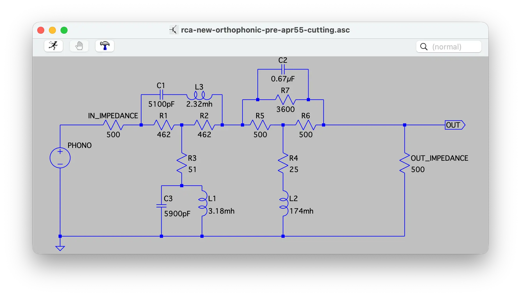
source: LTspice schematic reconstructed by the author from Notebook No.1 p.6 (top half, “Ortho Equalizer OLD TYPE”)
出典: Notebook 1, p.6 上半分 (OLD TYPE) の回路を筆者が LTspice で再現
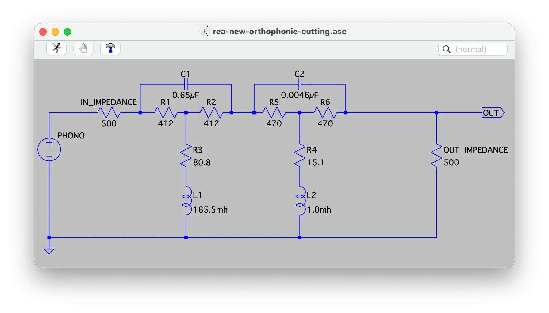
source: LTspice schematic reconstructed by the author from Notebook No.1 p.6 (bottom half, “NEW ORTHO from LAB 4-18-55”)
出典: Notebook 1, p.6 下半分 (NEW ORTHO from LAB 4-18-55) の回路を筆者が LTspice で再現
このページが社内の誰の目にも明らかに伝えているのは、OLD と NEW、すなわち旧回路と新回路の比較だ、ということです。ただし、両者は別物の回路ではありません。ともに Constant Impedance 500 Ω のもとでのブリッジド T 型の受動 LCR イコライザという、いわば同じ「型」 を共有しています。違うのは、その「型」 のなかで採用される個々の素子の値であり、特にインダクタとコンデンサの組み合わせ、つまりリアクタンス側の値の調整です。
The first thing this page communicates to anyone inside the company who looks at it is, quite plainly, that it’s a comparison between an OLD and a NEW circuit. But the two are not different beasts. Both are passive LCR equalizers in a bridged-T arrangement under a Constant Impedance of 500 Ω — they share the same underlying “shape.” What differs is the choice of individual component values within that shape, and in particular the combination of inductors and capacitors: the reactive side of the network.
ハイ側、すなわち高域を担うセクションでは、OLD では RCA 213R1 と書かれた 2.32 mH のインダクタが 1 個使われていました。NEW では、米国の部品メーカー Grayburne の可変インダクタ Varichoke (おそらく V-6 model: 0.65 mH 〜 6 mH の可変範囲) が 1 個、シャント部に置かれています。具体的なインダクタンス値については、まず黒いボールペンで「1.2 mh?」 と疑問符付きで書き入れられ、その下に赤い色鉛筆で「1.0 mh」 と書き加えられた、二段構えのメモが残されています。同じシャント部のすぐ近くでは、可変インダクタの直流抵抗値も赤い色鉛筆で「6.9 Ω」 と書かれたあと赤ボールペンで消され、「11.7 Ω」 に書き直されています。隣接する抵抗値も「19.9」 から「15.1 Ω」 へと書き直された痕跡が並んでおり、設計検討の試行錯誤と、最終的な合わせ込みの過程が、そのままノートのうえに残されている形です。量産機への展開を見据えた具体的な部品選定が、ノートのうえですでに動き出している様子が見て取れます。
On the high-frequency side of the network — the section handling the upper band — the OLD circuit used a single 2.32 mH inductor marked “RCA 213R1.” The NEW circuit instead places a variable inductor from the American component maker Grayburne — the Varichoke (probably the V-6 model, with a variable range of 0.65 mH to 6 mH) — in the shunt position. For the chosen inductance value, the page carries a two-layer note: first, “1.2 mh?” written in black ballpoint, with a question mark — still tentative — and then, below it, “1.0 mh” added in red colored pencil, evidently a later decision. Nearby, on the same shunt, the DC resistance of the variable inductor is recorded in red colored pencil as “6.9 Ω,” then crossed out in red ballpoint, with “11.7 Ω” written in its place. An adjacent resistor value has likewise been revised, from “19.9” to “15.1 Ω.” The trial-and-error of the design and the final tuning sit side by side, openly, on the same page. You can see, just from these traces, that the selection of specific components for the production machine had already begun, right there on the notebook.
ロー側、すなわち低域を担うセクションでも同様の動きがあります。OLD では UTC 製の V/C-7 と書かれた 174 mH の可変インダクタが使われていましたが、NEW では 165.5 mH / 14.4 Ω の固定値インダクタへと書き換わっています。可変から固定値へという方向性は、量産機での再現性 (同じ回路を組めば同じ特性が出るというラインを引きやすくすること) を志向するラボの姿勢の現れとも読めます。
The low-frequency side — the section handling the lower band — shows a similar movement. The OLD circuit used a UTC-made variable inductor labeled “V/C-7,” 174 mH. The NEW circuit replaces it with a fixed-value inductor of 165.5 mH / 14.4 Ω. The shift from variable to fixed reads, too, as a sign of the lab’s emerging concern with reproducibility on the production line — drawing a line by which the same circuit, assembled the same way, will reliably yield the same characteristic.
これらの素子値の見直しは、回路全体としての挿入損失 (Insertion Loss) にも反映されています。OLD では「-28 dB」 と 1 つの値が記されているだけですが、NEW では「31 to 33 db」 と、帯域内で 2 dB ほど変動するロスとして書かれています [注 1]。受動 LCR イコライザにおける挿入損失は、本来、特性カーブの形状によって帯域端と中域とで値が変わるのが自然です。OLD のような 1 値表記から、NEW のような帯域変動を含めた表記への移行は、設計者が回路の現実の振る舞いをより精密に記述するようになった、ということの現れでもあります。
These revisions of the component values are reflected in the circuit’s overall insertion loss as well. The OLD circuit gives just a single figure, “-28 dB”; the NEW one records “31 to 33 db” — a loss that varies by about 2 dB across the band [note 1]. In a passive LCR equalizer, the insertion loss naturally takes on different values at the band edges and the middle, depending on the shape of the response curve. The move from a single-figure notation like the OLD’s to a band-varying one like the NEW’s is itself a sign of the designer beginning to describe the actual behavior of the circuit with greater precision.
| 項目 Item | OLD | NEW |
|---|---|---|
| トポロジ Topology | Constant Impedance 500 Ω, bridged-T passive LCR (両者共通 / same) | |
| 高域インダクタ High-frequency inductor | RCA 213R1, 2.32 mH (1 個 / single) | Grayburne Varichoke .65–6 mH (V-6 model 想定 / presumed V-6 model) 黒「1.2 mh?」 → 赤鉛筆「1.0 mh」 black “1.2 mh?” → red pencil “1.0 mh” |
| 高域シャント DCR HF shunt DCR | — | 6.9 Ω → 11.7 Ω (赤ボールペンで書き直し / revised in red ballpoint) |
| 隣接抵抗 Adjacent resistor | — | 19.9 → 15.1 Ω (書き直し / revised) |
| 低域インダクタ LF inductor | UTC V/C-7, 174 mH (可変 / variable) | 165.5 mH / 14.4 Ω (固定 / fixed) |
| 挿入損失 Insertion Loss | -28 dB (単一値 / single value) | 31 to 33 dB (帯域内変動 / band-dependent) |
ここで一度立ち止まって、見落とされやすい論点を確認しておきます。OLD という呼称は、つい「RIAA 以前の何か」 と読みたくなるかもしれませんが、そうではありません。RCA Victor は 1952年8月の時点ですでに New Orthophonic、すなわち後の RIAA と完全に同じ時定数 (3,180 / 318 / 75 µs) で定義された目標カーブを採用しており、ここでの OLD と NEW はいずれも、その同じ目標カーブを実装するための、社内における旧バージョンと新バージョンの回路だと考えるのが正確です (詳しい時系列の位置付けは I.6 で扱います)。1949年に登場した RCA 45 回転盤の録音用 EQ である「Old Orthophonic」 とは別物であることも、ここで添えておきます。
Let me pause here on a point that is easy to misread. The label “OLD” might tempt one into reading it as “something from before RIAA” — but that is not what it means. By August 1952, RCA Victor had already adopted New Orthophonic, the target curve defined by the very same time constants (3,180 / 318 / 75 µs) that would later be ratified as RIAA. Both the OLD and the NEW circuits on this page are simply older and newer in-house implementations of that same target curve (the detailed timeline will come in I.6). It is also worth adding that this OLD is not the same thing as the “Old Orthophonic” — the recording EQ that appeared on RCA’s 45 rpm records in 1949.
言い換えれば、このページに書き留められているのは「新しい目標カーブへの初めての対応」 ではなく、「同じ目標カーブに対する、すでに何度目かの実装の作り直し」 です。回路構成は LCR ブリッジド T 型のまま据え置き、リアクタンス側の値だけを継続的に再計算しながら、量産機にも持っていける形へと精緻化していく。そういう RCA 内部の長期的な作業の、ある一断面が、この 1955年4月18日付のページなのです。
To put it another way: what’s set down on this page is not “a first response to a new target curve” but “another iteration of an already-iterated implementation of the same target curve.” With the LCR bridged-T shape held in place, only the reactive values recalculated again and again, the circuit is being refined into a form that can be carried over to the production machine. This page, dated April 18, 1955, is one slice of that long-running, in-house effort at RCA.
[注 1] 「31 to 33 db」 という表記は、もとは鉛筆で「33 db」 と 1 値だけが書かれていたものに、後から赤いペンで校正記号 “∧” (キャレット、挿入記号) を打ち、その上のスペースに「31 to」 を加筆して訂正した結果です。校正記号 “∧” は、英米の編集現場で広く使われる「ここに挿入してほしい」 を表す記号で、Chicago Manual of Style 等にも記載があります。ちなみに、このページを最初に AI に解析させた段階では、この赤い “∧” を取消線と読み違える幻覚がありました。最終的には、TIFF 原本を高解像度で拡大して私自身の目で再確認し、訂正に至っています。本シリーズで AI を補助として使ったときの落とし穴の、ささやかな一例です。
[note 1] The “31 to 33 db” notation came about like this: originally, only “33 db” had been written in pencil, as a single value. Later, a caret mark “∧” — the proofreader’s insertion symbol — was added in red ink, and “31 to” was written into the space above it as a correction. The caret “∧” is a widely used editorial symbol in the English-language publishing world for “please insert here,” documented in the Chicago Manual of Style and elsewhere. As an aside: when the page was first read through by an AI as my assistant, the red “∧” was misread as a strikethrough — a small hallucination. In the end, I went back to the original TIFF, enlarged it, and confirmed the mark with my own eyes. It is a modest example of the kind of pitfall worth watching for when an AI is used as a research assistant in this series.
I.5 Twenty-Two Rows, Within ±0.1 dB
ここまでに見てきた I.4 の素子値の比較は、いわば回路の「設計図」 のレイヤーでした。同じページのもう 1 つの主役、すなわち左下に縦に並んだ 22 行の周波数表は、その設計図の結果として実現される周波数特性、すなわち「実物の振る舞い」 を数字で記述したレイヤーです。
The comparison of component values that we worked through in I.4 was, in effect, the “blueprint” layer of the circuit. The other main character on the same page — the 22-row frequency table running down the lower-left corner — describes what comes out of that blueprint: the frequency response the circuit actually produces, written out as numbers. This is the “behavior in practice” layer.
表は 1 kHz を 0 dB の基準として、低域は 30 Hz まで、高域は 15 kHz まで、合計 22 ポイントの値が几帳面に縦に並んでいます。途中、3 kHz と 500 Hz の行は記入がなく、4 kHz から 2 kHz へ、700 Hz から 400 Hz へと直接飛んでいる箇所もあります。何かの理由で測定値の取得が漏れたのか、あるいはその時点では値の確認が不要だったのか。経緯までは現物からは追えませんが、この「飛び方」 もまた、ラボの机の上で実際に測定が進んでいた当時の雰囲気を伝えてくれます。
The table takes 1 kHz as its 0 dB reference, running from 30 Hz at the low end up to 15 kHz at the high end — twenty-two points in all, neatly stacked in a column. Two rows are conspicuously missing in the middle: there’s no entry at 3 kHz or 500 Hz, and the table jumps directly from 4 kHz to 2 kHz, and from 700 Hz to 400 Hz. Whether the measurements at those points were missed for some reason, or simply weren’t needed at that stage, isn’t something the page alone can tell us. But the very irregularity of the gaps somehow carries the atmosphere of the actual measurements being made, in real time, at a lab bench.
そして、この 22 行に並んだ値を、後の RIAA 標準 (時定数 3,180 µs / 318 µs / 75 µs) から計算した理論値と並べて見ると、思わず息を呑むような事実が浮かび上がってきます。帯域端と中域から数点だけ抜き出すと、こうなります。
And when the 22 values lined up in this table are placed alongside the theoretical values calculated from what would become the RIAA standard (time constants 3,180 µs / 318 µs / 75 µs), something quietly remarkable comes into view. Pulling out a few points from the band edges and the middle, the picture looks like this.
| Frequency (Hz) | RCA Notebook (dB) | RIAA Theoretical (dB) | Difference (dB) |
|---|---|---|---|
| 15,000 | +17.2 | +17.13 | +0.07 |
| 10,000 | +13.7 | +13.7 | ≈ 0 |
| 1,000 | 0 (ref) | 0 | 0 |
| 100 | -13.1 | -13.12 | +0.02 |
| 30 | -18.6 | -18.62 | +0.02 |
すべての行が、±0.1 dB 以内で一致しています。22 行の表全体を確認しても、この一致は崩れません。ノートの記入精度自体が小数点第 1 位までですから、これは「測定上区別がつかないほど一致している」 と言ってよい水準です。
Every single row agrees to within ±0.1 dB. Working through all 22 rows of the table, the agreement does not break anywhere. Since the notebook itself records values to one decimal place, this is the level at which one can fairly say “they match to within what the measurements can distinguish.”
ここで起きていることを、もう一度ことばにしておきましょう。1955年4月18日、RCA Victor 社内のあるラボで、誰かがブリッジド T 型の受動 LCR イコライザを組み、その出力をスイープしながら測定し、得られた値を几帳面にノートに書き留めました。その値は、その 1年3 ヶ月前 (1954年1月) に RIAA が承認していた録音再生特性の理論値と、測定器が区別できない範囲で一致していました。それを、その日のラボがその日のうちに、自分たちの手で確認していた、ということです。
Let me put into words, once more, what is happening here. On April 18, 1955, in a lab somewhere inside RCA Victor, someone assembled a bridged-T passive LCR equalizer, swept its output, measured the response, and wrote the resulting values, carefully, by hand, into the notebook. Those values matched the theoretical curve that the RIAA had approved as the recording and reproducing characteristic one year and three months earlier (in January 1954) — to within what the measuring equipment could distinguish. And the lab confirmed this with its own hands, on the very day this page was written.
ただし、ここで気をつけたいのは、この「一致」 は決して「初めての一致」 ではない、という点です。なぜそう言えるのかは、続く I.6 で、もう少し広い時系列のなかにこのページを置き直しながらお話します。
One important caution, though: this “match” is by no means a “first” match. Why I can say so will come in I.6, where I’ll place this page back into a slightly wider timeline.
I.6 Not “First Alignment,” but “Refinement”
I.5 で確認した周波数表と RIAA 標準値との ±0.1 dB 以内の一致は、それ自体としては息を呑むほど印象的な事実です。けれども、ここでひとつ、注意深く避けたい読み筋があります。それは「だから 1955年4月18日が、RCA Victor が初めて RIAA カーブと整合した日だ」 と読んでしまうことです。実際には、そうではありません。
The agreement between the frequency table and the RIAA standard to within ±0.1 dB, as we saw it in I.5, is, on its own, a quietly breathtaking fact. But there is one reading I would like to take care to avoid: namely, the reading that goes, “and therefore April 18, 1955 must be the day on which RCA Victor first aligned itself with the RIAA curve.” In fact, that is not what happened.
RCA Victor は 1952年8月の時点で、すでに「New Orthophonic」 と呼ばれる録音再生特性に切り替えています。この New Orthophonic は、後の 1954年1月に RIAA が承認することになる時定数 (3,180 µs / 318 µs / 75 µs) と完全に同一のものでした。すなわち RCA Victor は、RIAA 規格の登場よりも 1年5 ヶ月も前に、後の RIAA と数値的に一致するカーブを社内で目標として運用していたのです (この事実関係の詳細は、本サイトの FAQ「RIAA カーブはいつ策定されたか?」 のページにも整理してあります)。
By August 1952, RCA Victor had already switched over to a recording and reproducing characteristic it called “New Orthophonic.” The time constants of that New Orthophonic — 3,180 µs / 318 µs / 75 µs — were identical to those that the RIAA would go on to ratify in January 1954. In other words, a full year and five months before the RIAA standard appeared, RCA Victor was already operating, internally, a target curve that would later turn out to be numerically identical to what became RIAA (the detailed chronology of how this all fits together is laid out in the FAQ entry “When was the RIAA curve established?” on this site).
本稿で見ているノートの 1955年4月18日付という日付を、この時系列のなかに置き直してみましょう。
Let me set the April 18, 1955 date on the notebook page back inside that wider timeline.
1952年8月: RCA Victor、New Orthophonic 録音再生特性 (時定数 3,180 / 318 / 75 µs) を採用
1953年6月: NARTB が全面改訂で同一時定数を業界規格として正式採用
1953年7月: Moyer 氏が Audio Engineering 誌に New Orthophonic を解説する記事を発表
1954年1月: RIAA、同一時定数を録音再生特性として承認 (Bulletin E1)
1955年4月18日: 本 Notebook が記録された日 (RCA 社内ラボでの新回路実装の数値確認)
1957年2月: McLaughlin による RCA LCR 録音 EQ の手描き図 (Doug Pomeroy さん経由で、現在は Nick さんが保有)
August 1952: RCA Victor adopts the New Orthophonic recording and reproducing characteristic (time constants 3,180 / 318 / 75 µs)
June 1953: NARTB, in a full revision, formally adopts the same time constants as an industry standard
July 1953: Moyer publishes an article in Audio Engineering explaining the New Orthophonic
January 1954: The RIAA ratifies the same time constants as the recording and reproducing characteristic (Bulletin E1)
April 18, 1955: The day this notebook page was written (an in-house lab confirmation of the new circuit implementation at RCA)
February 1957: McLaughlin’s hand-drawn schematic of the RCA LCR recording EQ (passed down through Doug Pomeroy; currently in Nick Bergh’s holdings)
こうして並べてみると、1955年4月18日のラボでの確認作業は、目標カーブとの初対応どころか、RCA Victor が同じ目標カーブを採用してから数えて約 2年8 ヶ月後で、その間ずっと回路実装を継続的に練り上げてきた長期作業の、ある一断面であることが分かります。I.4 で見た OLD と NEW の関係についても同様で、OLD は「RIAA 以前の何か」 ではなく、1952年8月から 1955年4月までのあいだのどこかで一度組まれた、同じ目標カーブの旧バージョン回路だ、と読むのが正確です。
Set out this way, the lab confirmation on April 18, 1955 is anything but a “first response” to the target curve. It is, instead, a moment about two years and eight months after RCA Victor adopted that target curve — one slice of a long-running effort that had been steadily refining the implementation throughout. The same goes for the OLD/NEW relationship we looked at in I.4: the OLD is not “something from before RIAA,” but an older version of the in-house circuit for the same target curve, built at some point between August 1952 and April 1955.
言い換えれば、このページが教えてくれるのは、「同じ目標カーブを、回路構成の型は LCR ブリッジド T 型のままに据え置きつつ、リアクタンス側の値だけを継続的に再計算しながら、より精密に・より量産しやすく仕上げていった」 という地道な精緻化の過程です。本稿で繰り返し用いている「実装精緻化」 という捉え方は、ここから来ています。
To put it another way, what this page shows us is a patient process of refinement: keeping the LCR bridged-T circuit shape in place, recalculating only the reactive values, and gradually finishing the implementation into a form that is at once more precise and easier to put into mass production. The phrase I have been using throughout this piece, “implementation refinement,” comes from exactly this reading.
ここで、大事な告白を 1 つしておきます。本稿の素材を最初に読み解いていた段階で、私が補助に使っていた AI は、このページを「RIAA 整合のタイミングを示す一次史料」 と要約しました。事実関係の前後 (1952年8月の New Orthophonic 採用と、1954年1月の RIAA 承認との時系列) を、AI の側で (というのもおかしな比喩ですが) 取り違えていたためです。私がそれを読み返し、本サイトでこれまでに整理してきた史実関係や関連 FAQ にあたり直して訂正したことで、本稿で採用している「実装精緻化」 という捉え方は、ようやく確定しました。AI を補助として使うときの、ありふれた、しかし無視できない落とし穴の一例です。このことについては、I.8 の謝辞のなかで、もう一度短く触れます。
One important confession here. At the earliest stage of working through this material, the AI I was using as my assistant summarized the page as “a primary source pointing to the timing of RIAA alignment.” It turned out that the AI itself (an odd phrase to use, I admit) had gotten the chronology of the August 1952 New Orthophonic and the January 1954 RIAA the wrong way around. It was only after I went back through the page, cross-checked it against the historical record I had previously assembled on this site and the related FAQ entries, and rewrote the framing accordingly, that the reading I have been calling “implementation refinement” settled into place. An ordinary, but not negligible, example of the kind of pitfall that comes with using an AI as a research assistant. I’ll come back to this briefly in the acknowledgements at I.8.
I.7 What This Page Tells Us, What It Leaves Open
ここまで I.3〜I.6 で読み解いてきたことを、いったん私なりに整理しておきます。1955年4月18日付の RCA Notebook 1 冊目 6 ページが私に教えてくれた一番大きなことは、おおむね次のとおりです。
Let me draw together, on my own terms, what we’ve worked through in I.3 through I.6. The biggest things this single page — page 6 of RCA Notebook 1, dated April 18, 1955 — has told me are, roughly, as follows.
1つめは、これが 1952年8月以来の長期的な実装精緻化作業の、ある一断面を写した記録であるということ。同じ目標カーブ (New Orthophonic、後の RIAA) のもとで、回路構成は LCR ブリッジド T 型のまま据え置きつつ、リアクタンス側の値だけを継続的に再計算していく、そういう RCA 内部の地道な作業の流れの、ある特定の日のスナップショットです。
First: that this page is a single slice of a long-running implementation-refinement effort that had been underway since August 1952. Under the same target curve (New Orthophonic, later RIAA), the team kept the LCR bridged-T circuit shape in place while continuously recalculating only the reactive values. The page is one particular day’s snapshot of that steady, in-house work at RCA.
2つめは、それでもこの 1 ページが、「RCA 社内で、自社のラボ自身の手によって、New Orthophonic の実装値が後の RIAA 標準と数値的に完全一致することを確認していた」 という事実の、文書としての裏付けになりうること。同種の社内文書が一般にはほとんど公開されていないなかで、こうした「日付つき・数値つき」 の確認記録が手元にあるというのは、私にとっては小さくない出来事でした。
Second: that, even so, this single page can serve as documentary support for the fact that, inside RCA, by the lab’s own hands, the company had verified that the implementation values for New Orthophonic numerically matched what would become the RIAA standard. Given how little of this kind of in-house material has ever been made public, having a dated, numbered confirmation like this in my own hands has not been a small thing for me.
3つめは、NEW 回路の脇に書き添えられた「Grayburne varichoke .65-6 mh」 というメモが、ラボの机の上だけに留まらず、量産機への実装を見据えた具体的な部品選定が動き出していたことを示唆していること。社内ラボの机上の精緻化が、その先の量産機まで届く動線が、すでにここで見え隠れしています。
Third: that the marginal note “Grayburne varichoke .65-6 mh” jotted alongside the NEW circuit hints that concrete component selection — with an eye on the production machine, not just the lab bench — had already begun. The path from bench-level refinement inside an in-house lab toward an actual production machine starts to become visible, right here on the page.
一方で、1 ページの文書からは答えが出ない、あるいは別の史料を待たないと判断できない問いも、いくつか同時に持ち帰ることになりました。本稿ではそれらに結論を出さないかわりに、これから先の探究のためのフロンティアとして、4 つだけ書き留めておきます。
At the same time, the page also leaves me carrying away a number of questions that one page alone cannot answer, or that can’t be settled without other sources surfacing. Rather than try to close them, I’ll set them down here as four open frontiers for further inquiry.
(1) OLD 回路の正確な日付付け: OLD 回路は 1952年8月から 1955年4月までのあいだのどこかで一度組まれたバージョンですが、それがいつの版なのかは、本ページだけからは特定できません。本 Notebook の収録範囲は 1955年3月11日以降なので、OLD はそれ以前の別の手控え (より古い Notebook、ラボメモ、社内技術文書など) に記録されていたものを参照したかたちと考えられます。Doug Pomeroy さんから Nick さんが引き継いだコレクション全体のなかに、あるいは別の RCA Engineering Department の史料群のどこかに同じ素子値が現れれば、OLD の日付がより精度よく定まる可能性があります。
(1) Dating the OLD circuit precisely. The OLD circuit is a version assembled at some point between August 1952 and April 1955, but this page alone doesn’t pin down which version it is. Since this notebook itself only goes back to March 11, 1955, the OLD circuit must have been recorded in earlier paperwork elsewhere — an older notebook, lab memos, internal technical documents. If the same component values were to surface somewhere in the wider collection Nick inherited from Doug Pomeroy, or in another set of RCA Engineering Department materials, the OLD’s date might come into sharper focus.
(2) Grayburne Varichoke の量産機への展開: NEW 回路図に書き添えられた Grayburne Varichoke .65-6 mh が、RCA の量産カッティングマシン (RCA 76-D、RCA 78-A など) に実際にどう実装されたかは、まだ追跡できていません。これらの機種のサービスマニュアルや部品表に同じ部品が見つかれば、本ノートのラボ精緻化と量産機との直接の系譜が、ぐっと裏付けの取れた線で繋がります。
(2) The Grayburne Varichoke’s reach into production machines. Where the Grayburne Varichoke .65-6 mh noted in the margin of the NEW circuit ended up appearing in RCA’s production cutting lathes (the RCA 76-D, the RCA 78-A, and so on) is something I haven’t yet been able to trace. If the same part shows up in the service manuals or parts lists of those machines, the line connecting the bench-level refinement on this notebook page to the production floor would become firmly documented.
(3) 1957年 McLaughlin 手描き図との関係: Nick さんが ARSC 2022 で一瞬スライドに映していた、1957年 RCA の LCR 録音 EQ の McLaughlin による手描き図。これと本ノートとの系譜関係も、興味深いフロンティアです。1955年4月のラボ精緻化と、その約 2年後の McLaughlin 図のあいだで、回路実装はどう進化したのか。Doug Pomeroy さんから Nick さんが引き継いだコレクション全体の像とも繋がる、より大きな問いの一部でもあります。
(3) The lineage to the 1957 McLaughlin hand-drawn schematic. McLaughlin’s hand-drawn schematic of the 1957 RCA LCR recording EQ — the one Nick flashed briefly on a slide during ARSC 2022 — is another open frontier. How did the circuit implementation evolve between the lab refinement of April 1955 and the McLaughlin schematic some two years later? That question is itself part of a larger one — about the whole collection Nick inherited from Doug Pomeroy.
(4) Early RIAA graph の dating: Nick さんから 4月に一括送付されてきた史料群の中の 1 枚、手書きの “RECORDING CHARACTERISTIC RIAA / CONSTANT VEL. BASIS / RECORD INDUSTRY ASSN. AMERICA” と書かれたグラフは、日付が記されていないものの、紙質や手書きの古さから 1950年代前半と推定されます。プロット範囲も高域側が 15 kHz 直前で打ち切られており、これは IEC 拡張 (1976) 以前の 15 kHz 上限時代と整合します。本グラフが RIAA Bulletin E1 (1954/1) のオリジナル文書 (またはその直接の手控え) の一部である可能性も完全には排除できません。Bulletin E1 そのものの現物は、Nick さんの手元にもなく、私もまだ確認できずにいます。本グラフがその「最も近いだろうもの」 として手元にあること、その先にもう一歩踏み込んで日付を特定できるかどうかは、本稿が残したフロンティアのひとつです。
(4) Dating the early RIAA graph. Among the photographs Nick sent in April was a hand-drawn graph labeled “RECORDING CHARACTERISTIC RIAA / CONSTANT VEL. BASIS / RECORD INDUSTRY ASSN. AMERICA.” It carries no date, but the paper and the handwriting make it visibly an early-1950s document. The plot itself stops just short of 15 kHz on the high end — consistent with the era of the 15 kHz upper bound, before the IEC extension of 1976. The possibility that this graph is a part of the original copy of RIAA Bulletin E1 from January 1954 (or one of its direct desk copies) cannot be ruled out entirely. Bulletin E1 itself is not in Nick’s hands either, and I haven’t yet been able to lay my hands on it. That this graph sits with me as the “closest thing to it” I have, and whether anyone can take its dating one step further, is itself one of the frontiers this piece leaves open.
 desk copy | microgroove.jp")
source: courtesy of Nicholas Bergh. A hand-drawn graph labeled “RECORDING CHARACTERISTIC RIAA / CONSTANT VEL. BASIS / RECORD INDUSTRY ASSN. AMERICA” — date unknown, possibly part of the original copy of RIAA Bulletin E1 (January 1954) or one of its direct desk copies
出典: Nicholas Bergh さん提供。”RECORDING CHARACTERISTIC RIAA / CONSTANT VEL. BASIS / RECORD INDUSTRY ASSN. AMERICA” と書かれた手書きグラフ。日付なし、Bulletin E1 (1954) のオリジナル文書 (またはその直接の手控え) の1枚である可能性も完全には排除できない
これらのフロンティアについて私に答えがあるわけではありません。本稿はあくまで、ある 1 ページのノートを起点として、そこから見えるものとそこからは見えないものを切り分け、見えないものについては「これは未解明である」 と書き残すところまでで、ひとまず形を閉じておきたいと思います。続きのピースは、本シリーズの今後の Liner Notes II 以降か、あるいは同じ史料への関心を共有してくださる方々の手によって、どこかで埋まっていくかもしれません。
I have no ready answers to any of these frontiers myself. What this piece is trying to do, starting from one page of a notebook, is simply to separate what can be seen from what cannot, and, for the things that cannot, to write down a clear marker that says “this is still unknown” — and then to close the shape there, for now. The pieces that remain may, in time, be filled in by future installments of this series, Liner Notes II and onward, or by others who happen to share an interest in this same source.
このページについて、別の読み方や、別の史料との接続をご存じの方がいらっしゃれば、ぜひお寄せいただけたら嬉しく思います。
If you happen to know of another way to read this page, or of another source it connects to, I would be very glad to hear from you.
I.8 Acknowledgements
本稿が成り立つにあたっては、まず何より、Nicholas Bergh さんに心からの感謝を申し上げたいと思います。1955年4月18日付の Notebook 1 冊目 6 ページという、いまや比較的入手の難しいクラスの史料を、惜しみなく私に共有してくださいました。本シリーズ第 1 弾を、Nick さんから渡された 1 枚の写真からはじめられたことは、私にとってこのうえない幸運です。
Above all, this piece could not have come into being without Nicholas Bergh, to whom my heartfelt thanks go first. The page in question — page 6 of Notebook 1, dated April 18, 1955 — belongs to a class of in-house material that is, today, fairly hard to come by, and he shared it with me without reservation. To be able to launch the first installment of this series from a single photograph passed to me by Nick is, for me, an extraordinary piece of good fortune.
あわせて、ARSC (Association for Recorded Sound Collections) のコミュニティに対して、改めて謝意を記しておきたいと思います。Nick さんとのやりとりが続いてきた背景にも、Nick さんが ARSC のカンファレンスで重ねてこられた発表があり、私自身も ARSC 会員として、メーリングリスト ARSC-L での日々のやりとりや、各種カンファレンス資料へのアクセスを通じて、多くのことを学ばせていただいています。本稿のような史料をめぐる作業は、ARSC のような会員相互の交流の場があってはじめて成り立ちうるものだ、と日々実感しています。
In the same spirit, I’d like to record my thanks once again to the community of the ARSC (Association for Recorded Sound Collections). Behind my correspondence with Nick lies the series of presentations he has given at ARSC conferences over the years; and as an ARSC member myself, I have learned a great deal from the daily exchanges on the ARSC-L mailing list and from access to conference materials. Work like this, around archival sources, becomes possible in the first place only because spaces like ARSC — built on mutual exchange among members — exist. That is something I find myself recognizing again and again.
また、ディスク録音史をめぐるさまざまな場面でいつも示唆を与えてくださっている Tom Fine さんのお名前も、ここで併せて記しておきたいと思います。
I would also like to add the name of Tom Fine here, who has, across many corners of disc-recording history, given me thoughtful guidance time and again.
これまで Pt.0〜Pt.25 の連載は、私が自分だけで調査し、自分だけで書いてきたものでした。一方で、新しい 「フォノイコライザカーブの歴史」 セクション、および本シリーズ Liner Notes の執筆にあたっては、Anthropic 社の AI である Claude を補助として併用しています。I.6 で触れた取り違えの訂正を含め、本稿は人間と AI の協働として書かれています (生成 AI を本サイトの制作でどのように使っているかについては FAQ 本サイトの制作で生成 AI をどのように使っているか にまとめています。また、本テーマ自体については、本シリーズの続編 Liner Notes II 以降で改めて整理してみる予定です)。
The Pt.0–Pt.25 series, up to now, was something I researched and wrote entirely on my own. For the new “The History of Phono EQ Curves” section, and for this Liner Notes series, however, I have been using Anthropic’s AI, Claude, as an assistant alongside my own work. The correction described at I.6 is one example; this piece is written as a collaboration between a human and an AI. (How generative AI is used in producing this site is laid out in the FAQ entry “How generative AI is used in producing this site.” I also expect to return to the topic itself in future installments of this Liner Notes series, from Liner Notes II onward.)
I.9 Related Links
本稿の議論を、本サイトの他のページや外部資料と接続するためのリンクをまとめておきます。
A small collection of links, here, to connect the threads of this piece to other pages on this site and to outside sources.
本シリーズ本編「Things I learned on Phono EQ Curves」 のなかから:
- 「Pt.3 (Blumlein システム、当時の RCA や Columbia、民生用における高域プリファレンスの萌芽)」: Nick さんが本シリーズに初めて登場するセクション 3.1 を含む
- 「Pt.5 (ベル研とストコフスキーのエピソード、横振動トランスクリプション、Orthacoustic カーブ)」: Orthacoustic / New Orthophonic の系譜を遡る前史
- 「Pt.18 (1953 NARTB / 1954 改訂 AES / 1954 RIAA 規格策定の歴史)」: 本稿 I.6 の時系列の絵に登場する規格策定史
- 「Pt.19 (1950年代中盤以降の録音アンプや録音 EQ の仕組みの調査)」: 1955年前後の録音 EQ 実装をめぐる広い文脈
- 「Pt.23 (1970年代民生用アンプ内蔵フォノイコの RIAA 偏差、その他)」: セクション 23.2 で LCR と RC の対比、および Nick さんとのメールやりとりからの抜粋を多く掲載
From the main series “Things I learned on Phono EQ Curves”:
- Pt.3 (the Blumlein system; RCA and Columbia at the time; early signs of a high-frequency preference in consumer playback): includes §3.1, where Nick first enters this series
- Pt.5 (Bell Labs and the Stokowski episode; lateral transcription discs; the Orthacoustic curve): the prehistory tracing the Orthacoustic / New Orthophonic lineage further back
- Pt.18 (the history of the 1953 NARTB / 1954 AES revision / 1954 RIAA standard formulation): the standards-formulation history that appears in this piece’s timeline at I.6
- Pt.19 (a study of recording amplifiers and recording EQ implementations from the mid-1950s onward): the wider context of recording-EQ implementations around 1955
- Pt.23 (RIAA deviations in 1970s consumer integrated phono preamps, and related topics): §23.2 contrasts LCR and RC, and includes many excerpts from email exchanges with Nick
本サイトの FAQ ページから:
- 「技術者は協力していたのに、なぜ Columbia と RCA Victor は別々の規格を出したのか?」: Columbia LP と RCA 45 が別規格として登場した 1948-1949年の規格戦争。技術者協力と経営対立の二層構造
- 「RIAA カーブはいつ策定されたか?」: 本稿 I.6 で参照した、1952年8月の RCA Victor New Orthophonic 採用と 1954年1月の RIAA 承認との時定数同一性についての整理
- 「RIAA カーブとは?」: RIAA 規格全般の解説
- 「規格文書の時定数表記は LCR から RC にいつ書き換わったのか?」: 規格文書の側で LCR から RC へ表記が移っていった史実の整理
- 「カッティング EQ を完全に打ち消す再生 EQ はあるのか?」: 本 Notebook の sim を含む詳細な技術解説。Nick さんが提供してくださった図版のキャプションからも、本 Liner Notes I へリンクを置いてあります
From the FAQ pages on this site:
- Why did Columbia and RCA Victor release separate formats if their engineers were cooperating?: the 1948-1949 format war that brought the Columbia LP and the RCA 45 out as separate standards — a two-layer structure of engineer-level cooperation and management-level rivalry
- When was the RIAA curve established?: the chronology referenced in I.6 of this piece, including the identical time constants of RCA Victor’s August 1952 New Orthophonic and the January 1954 RIAA ratification
- What is the RIAA curve?: a general account of the RIAA standard
- When did the standards documents change their wording from LCR to all-RC?: the history of how the time-constant notation in the standards documents shifted from LCR to RC
- Can a Playback EQ Perfectly Cancel a Cutting EQ?: a detailed technical treatment that includes the simulation of this Notebook. A figure caption provided by Nick also links back from there to this Liner Notes I
Nicholas Bergh さん関連:
- 「Understanding Errors in Archival Phono EQ Standards by Looking at Original Disc Recording Equipment」 (ARSC Conference 2022 オンライン発表、ARSC 会員のみ閲覧可能)
Related to Nicholas Bergh:
- Understanding Errors in Archival Phono EQ Standards by Looking at Original Disc Recording Equipment (ARSC Conference 2022 online presentation; viewable for ARSC members only)
このページに残された、いくつかの数字、いくつかの素子値、そして手描きの回路図。そのすべてを、私ひとりで読み切ってしまうのは惜しい気がしています。本稿で見えたこと・残したことのいずれについても、別の解釈、別の史料、別の物語をご存じの方からの応答を、心からお待ちしています。
The numbers, the component values, and the hand-drawn circuit — all of it left on this single page. I find myself a little reluctant to read it through entirely on my own. For everything this piece has been able to see, and for everything it leaves open, I am genuinely hoping for responses — different interpretations, different sources, different stories — from anyone who shares an interest in this material.
» Phono EQ Curves Liner Notes II-a へ続く »
» Phono EQ Curves Liner Notes II-a, to be continued »