EQカーブの歴史、ディスク録音の歴史を学ぶ本シリーズ。前回 Pt.18 では、1953 NARTB / 1954 改訂 AES / 1954 RIAA という、現代につながる録音再生標準特性の成立の歴史を追いました。
On the previous part 18, I learned the history of formulation of the following standards: 1953 NARTB Recording and Reproducing Standards; 1954 new AES Playback Curve; 1954 RIAA Standard Recording and Reproducing Characteristic.
今回の Pt.19 では、1950年代〜当時、スタジオで使われていた録音用機材などについてみていき、録音機材の側面から録音EQカーブについて考えてみます。
In this Pt. 19, we’re going to learn the recording equipment used at that time in the 1950s and beyond, thus learning the recording EQ curves from the recording equipment’s viewpoint.

source: GOTHAM PFB-150WA Power Amplifier (YouTube)
YouTube ビデオより拡大。「FLAT」「78」「33 1/3」「45」のポジションと、それぞれのスクリュードライバ微調整ノブが確認できる
本稿は以下の続きです。
- 「Pt.0 (はじめに)」
- 「Pt.1 (定速度と定振幅、電気録音黎明期)」
- 「Pt.2 (世界初の電気録音、Brunswick Light-ray、ラジオ業界の脅威)」
- 「Pt.3 (Blumlein システム、当時のRCAやColumbia、民生用における高域プリファレンスの萌芽)」
- 「Pt.4 (Vitaphone、Program Transcription、Electrical Transcription、Bell Labs / Western Electric 縦振動トランスクリプション盤)」
- 「Pt.5 (ベル研とストコフスキーのエピソード、横振動トランスクリプション、Orthacousticカーブ)」
- 「Pt.6 (アセテート録音機のカッターヘッド特性、高調波歪の論文、超軽量ピックアップ)」
- 「Pt.7 (圧電ピックアップとジュークボックス、定速度記録再生の試み)」
- 「Pt.8 (1942年 NAB 標準規格策定の歴史)」
- 「Pt.9 (大戦中〜戦後、LP登場前夜の状況について)」
- 「Pt.10 (1949年 NAB 標準規格策定の歴史)」
- 「Pt.11 (1948年6月18日 Columbia LP Microgroove レコード登場)」
- 「Pt.12 (Columbia LP の技術的背景)」
- 「Pt.13 (RCA Victor 45回転システムの登場と技術的背景)」
- 「Pt.14 (回転数競争と各レーベルの参入状況)」
- 「Pt.15 (「ハイ・フィデリティ」という用語の歴史)」
- 「Pt.16 (「サファイア・グループ」と学会「AES」、AES再生カーブ)」
- 「Pt.17 (RIAA以前の米国各レーベルの使用EQカーブ調査)」
- 「Pt.18 (1953 NARTB / 1954 改訂 AES / 1954 RIAA 規格策定の歴史)」
This article is a sequel to:
- “Things I learned on Phono EQ curves, Pt.0 (Intro)”,
- “Pt.1 (constant velocity/amplitude, early years of electrical disc recording)”,
- “Pt.2 (earliest electrical recordings, Brunswick Light-ray, Radio industry)”,
- “Pt.3 (Blumlein system, RCA and Columbia in the early 1930s, germination of treble pre-emphasis)”,
- “Pt.4 (Vitaphone, Program Transcription, Electrical Transcriptions, Bell/WE Vertical Transcription)”,
- “Pt.5 (Bell Labs = Stokowski episode, Lateral Transcription and Orthacoustic)”,
- “Pt.6 (Instantaneous Recorders, papers on distortion and lightweight pickup)”,
- “Pt.7 (piezo-electric pickups, jukebox, constant-amplitude recording)”,
- “Pt.8 (history of 1942 NAB Standards)”,
- “Pt.9 (various situations in the 1940s)”,
- “Pt.10 (history of 1949 NAB Standards)”,
- “Pt.11 (Jun. 18, 1948: the advent of Columbia Long Playing Microgroove Records)”,
- “Pt.12 (technical background of Columbia LP records)”,
- “Pt.13 (Jan. 10, 1949: the advent of RCA Victor 45 rpm system, and its technical background)”,
- “Pt.14 (1949-1950: “The Battle of The Speeds” and the entry status of various labels)”,
- “Pt.15 (History of the term “High Fidelity”)”,
- “Pt.16 (“Sapphire Group” and “Audio Engineering Society”; 1951 AES Curve)”,
- “Pt.17 (Survey of the EQ Curves used by the U.S. labels before the RIAA formulation)”,
- and “Pt.18 (History of the 1953 NARTB / 1954 new AES / 1954 RIAA Standards)”.
毎回書いている通り、筆者自身の学習過程を記したものですので、間違いの指摘や異論は遠慮なくお寄せください。
As I noted in every part of my article, this is a series of the footsteps of my own learning process, so please let me know if you find any mistakes on my article(s) / if you have different opinions.
いつものように長くなってしまいましたので、さきに要約を掲載します。同じ内容は最後の まとめ にも掲載しています。
Again, this article become very lengthy — so here is the summary of this article beforehand (the same summary are avilable also in the the summary subsection).
RIAA 規格策定後、民生用再生システムだけではなく、プロ用録音システムも、ディスク録音は RIAA 特性を前提としたものに変わっていった。
After the formulation of the RIAA Standards, not only consumer reproducing systems but also professional recording systems changed to meet the RIAA Recording/Reproducing Characteristic for disc recording.
1950年代〜1970年代のさまざまなディスク録音システムの回路図や取説を調査してみると、そのほとんどがアンプ内に巧妙な仕組みで RIAA 録音イコライザ回路を持っていることが分かった。また、アンプ内のモニタ用再生イコライザ回路も RIAA だった。
A study of many schematics and instruction manuals for various disc recording systems from the 1950s to 1970s revealed that, most of them had RIAA recording equalizer circuits inside the amplifiers dexterously. Also, the monitor playback amplifiers built in these systems had RIAA reproducing EQ circuits.
これらの録音システムでの RIAA 以外の録音特性の適用は、技術的には不可能でないものの、非現実的であるという感想を持った。
The construction of these recording systems seemed (for me) to make it virtually impractical to change the RIAA recording characteristics to others, although it was “technically possible”.
RIAA 録音特性を使いつつも、リミッタやコンプレッサなどを使い、低域を増幅し、高域を減衰させる特性でカッティングするというプラクティスは、ジュークボックス向けなど主に45回転盤用に広く行われていた。Fairchild Model 644 カッティングアンプは、それ専用のポジションも備えていた。
The practice of using a limiter or compressor to amplify the low frequencies and attenuate the high frequencies, while using the RIAA recording characteristic, was widely common for 45 rpms, especially for jukeboxes. Fairchild Model 644 amplifier had such a recording EQ position dedicated to this purpose.
その他、Westrex RA-1700 録音システムの RA-1706 のように、カッティング時に高域減衰するユニットも広く使われていた。
Other example was the Westrex RA-1706 High Frequency Reduction Amplifier (an intelligent low-pass equalizer unit for the RA-1700 System), that was widely used in the recording chain at the time.
Contents / 目次
- 19.1 After the Formulation of the RIAA Recording Curve
- 19.2 Disc Recording Equalizers at the time
- 19.2.1 Cinema Engineering Type 7095 Recording Equalizer
- 19.2.2 Gotham PFB-150WA Recording Amplifier
- 19.2.3 Fairchild Model 641 Stereophonic Disk Recording System
- 19.2.4 Westrex RA-1514 Recording Equalizer
- 19.2.5 Westrex RA-1574-B Amplifier
- 19.2.6 Westrex RA-1574-D Amplifier
- 19.2.7 Westrex RA-1703 Input Amplifier
- 19.2.8 Neumann LV60 Power Amplifier
- 19.2.9 Neumann VE-66S / VG-66 Amplifier System
- 19.2.10 Ortofon GO-741 Cutting Amplifier
- 19.3 Thought Experiment: To Accomplish non-RIAA with Those Equipment
- 19.4 The summary of what I got this time / 自分なりのまとめ
19.1 After the Formulation of the RIAA Recording Curve
前回の Pt.18 でみたように、1954年1月29日、RIAA 技術委員会が提出した企画文書 “RIAA Standard Recording and Reproducing Characteristic” が、無事 RIAA 理事会に承認されました(Pt.18 セクション 18.5.5 および セクション 18.5.6 参照)。
As we already have learned in the previous Pt.18, RIAA Engineering Committee submitted the “RIAA Standard Recording and Reproducing Characteristic”, and the submission was successfully approved by the RIAA board of directors (see: Pt.18 Section 18.5.5 and Section 18.5.6).
もちろん、レコード業界自らの手で策定した標準規格が完成したからといって、ある日を境に米国の全レーベルが一斉に RIAA 録音カーブにスイッチした(スイッチできた)わけではありません。移行は徐々に行われました。
Of course, the formulation of the standard established by the record industry itself does not mean that all the U.S. labels instantly switched to the RIAA Recording Curve overnight. The transition to the RIAA recording characteristics was gradual.
そもそも、あたかも民生用可変フォノイコのように、複数の録音カーブ向けのパラメータをダイヤル式で手軽に切り替える、そんなディスク録音イコライザは米国において1950年代以降は存在していませんでした(今もありませんよね)。録音現場で使われていた録音イコライザは、原則として特定の録音カーブ向けの固定式ユニットでした。
To begin with, there was (and still is) no such thing as a disc recording equalizer from the 1950s and beyond in the U.S., that could easily switch between multiple pre-defined curves and parameters with dials, as if it were a consumer-use (archival) variable phono equalizer. The recording equalizers used in the professional recording studios were, in principle, fixed units for specific recording curves.
せいぜい、あったとしても、特定の単一録音特性のポジションと、テストカッティングによる較正(キャリブレーション)用のフラットポジションの切り替え、そして微調整ノブくらいでした(後述)。
At best, there was a switch between a position for a specific recording characteristic and a FLAT position for calibration by test cutting, plus fine-tuning screw knobs (all of which will be discussed later in this article).
本記事公開直前に、ある雑誌に掲載された可変式ディスク録音イコライザの記事を偶然発見しました。1954年の Fairchild 639 可変録音イコライザ です。既定の録音カーブ複数間で選択可能な製品が存在していたことにびっくりする一方、「RIAA規格前後に登場した」同様の可変録音イコライザの情報は、依然としてこの Fairchild 639 以外に見つけられていません。
Just prior to the publication of this Pt.19 article, I stumbled across an article in a magazine, on variable disc recording equalizers: Fairchild 639 from 1954. I was surprised that such a product actually existed that could switch among a set of given recording EQs. However, at the same time, I have not been able to find any other information than this yet, on similar variable recording equalizers from the period “just before and/or after the formulation of the RIAA Standards”.
 | microgroove.jp")
source: “RECORDING EQUALIZER offers a choice of 5 curves”, Electronics, September 1954, p. 311.
The only information I could find of “variable” “recording” EQs “from the mid-1950s and beyond”
現時点で唯一見つけた、「1950年代中旬またはそれ以降の」「可変」「録音」イコライザの情報。
カーブは「AES」「LP」「NARTB」のほか、フラット特性、「中間特性」(詳細不明)があった模様。
639A は挿入損失が 24dB だが、639B は 16dB ゲインのブースタアンプ内蔵、とある
それに、1954年9月時点での「AES」は「1954 改訂AES」を指すはずで、「1953 NARTB」および「1954 RIAA」と同じなのですが、そうするとなぜ「NARTB」ポジションが別にあるのか謎です。「AES」ポジションが旧AESを指す場合も、なぜ1954年9月にそのような古い録音カーブ用ポジションを用意したのか、意図が分かりません。そのような意味でも謎多い仕様となっています。
What’s more, “AES” as of Sep. 1954 should be the new AES Playback Characteristic which corresponds to “1953 NARTB Recording Characteristics” and “1954 RIAA Recording/Reproducing Characteristics”. If so, it is a mystery why “NARTB” position is also there. Also, if the “AES” position denotes the recording characteristics that corresponds to the old 1951 AES Playback Standard, I have no idea why Fairchild prepared such old (and obsolete) recording position in September 1954. In this sense, the specifications are a mystery.
また、この Fairchild 639 については、現物写真やパンフレット、取説が一切確認できないなど、この記事以外に全く情報が見つからず、実際に製品化されたのか、現場で利用されたのか、も不明で、詳細は闇の中です。
Also, this article is the only information I could find on Fairchild 639 — I am unable to find any actual photos of the product, brochures or instruction manuals — not at all. Not sure if it was actually manufactured and released, not sure if it was actually used in the studios. The details are still in the dark.
録音カーブを変更する現実的な方法は、独立した録音EQユニットを別のものに交換する、あるいは、録音EQが内蔵された録音用アンプごと交換したり、録音システム全体を交換するしかありません。
The only practical ways to change the recording curve is, to replace the independent recording EQ unit with another one, or to replace the entire recording amplifier with built-in recording EQ, or to replace the entire recording system.
しかも時代は戦後、マイクログルーヴ盤が登場し、ディスク録音の技術革新がどんどん進んでいた時期です。限られた大手レーベルだけが最先端のカッティング技術を自社開発していた時代は過ぎ、独立系録音スタジオがどんどん生まれ、それに呼応するようにプロフェッショナル向けの録音機材がどんどん登場していた時期です。そして、録音再生EQカーブに限らず、レコード盤の形状や溝の断面形状、その他多くの技術的側面の標準規格化が一気に進んでいた時期です。
Moreover, the postwar period was a time of rapid technological innovations in disc recording, with the advent of microgroove records. The era when only a limited number of major labels were developing cutting-edge technology in house was over, and independent recording studios were springing up, and professional recording equipment was being introduced rapidly in response. This was also a time when the standardization of not only recording/reproducing EQ curves, but also disc shapes, record groove shape and other technical aspects were being standardized at a rapid pace.
独立系スタジオやマイナーレーベル所有のスタジオなどは、資金も潤沢ではなかったでしょうから、RIAA規格策定後の機材リプレースに二の足を踏んだことも想像されます。
It can be imagined that independent studios and studios owned by minor labels were hesitant to quickly replace their equipment after the RIAA Standard was established, probably because they did not have ample funds.
1950年代前半までは、既存のカッターヘッドを自力で改造したり、録音EQユニットを自力で開発したエンジニアがいたかもしれませんが、品質コントロールの側面からも、プロフェッショナル市場用専門メーカが製造したものを調達したエンジニアが大半だったはずです。
There might have been some engineers who modified existing cutterheads by themselves or developed recording EQ units by themselves, especially until the early 1950s. However, from the aspect of quality control, the majority of engineers would have procured the products manufactured by specialized manufacturers for the professional market.
その上で、カッターヘッドやカッターレース、録音アンプと組み合わせてテストカットと較正を行い、本番投入していた、と考えるのが自然でしょう。
And it is natural to assume that, after the installation and configuration of the equipment, test cuts and calibrations were then made in combination with cutterheads, cutting lathes, and recording amplifiers, and then put into production.
1950年代中盤以降でも、プロ用機材を改造して使っていたエンジニアの例も一部知られています。
Some examples of engineers are known who modified and used professional equipment even after the mid-1950s.
Fine Recording の C. Robert Fine 氏は、ステレオ時代が進んでも Westrex 3D カッターヘッドを使わず、オリジナルの Westrex 3A カッターヘッドのサスペンションを改造してフィードバックを使わずに使用し続けていました。また、McIntosh 録音用パワーアンプも改造して使っていたそうです。 (出典: “Behind The Scene: The Professional Viewpoint. A dialogue with Bob Fine”, Audio, Nov./Dec. 1968, pp.8-12,100-103.)
Even after the advent of 45/45 stereo discs, it is known that Mr. C. Robert Fine of Fine Recording did not use Westrex 3D cutterheads. He insisted to use Westrex 3A with its suspension modified by themselves, and he did not use feedback. Furthermore, Fine Recording used 200Wx2 modified McIntosh as their cutting amplifiers. (source: “Behind The Scene: The Professional Viewpoint. A dialogue with Bob Fine”, Audio, Nov./Dec. 1968, pp.8-12,100-103)
FINE: We modify the suspension of the 3A ourselves. We don’t use feedback. We use something else because we don’t believe in feedback, especially the Westrex feedback system, because that is not a true way to correct mechanical motion.
FINE氏: 我々は (Westrex) 3A のサスペンションを自ら改造している。フィードバックは使っていない。フィードバック技術、特に Westrex のフィードバックシステムは信用していない、なぜなら機械的な動きを補正する正しいやりかたではないからだ。だから我々は(フィードバックではない)別の方法を使っている。
“Behind The Scene: The Professional Viewpoint. A dialogue with Bob Fine”, Audio, Nov./Dec. 1968, pp.8-12,100-103このような取り組みをしていたエンジニアもいたのは事実ですが、やはり少数派だったと考えられます。ましてや、RIAA規格策定後に録音イコライザの改造を行ったエンジニアの話は聞いたことがありません。
So there actually were some (exceptionally talented) engineers who did their own modifications, but I guess they were in the minority. Furthermore, I have never heard of any engineer(s) who had modified the recording equalizers AFTER the formulation of the RIAA Standards.
19.2 Disc Recording Equalizers at the time
では、今回はまず、1954年の RIAA 策定当時、そしてその後、当時プロフェッショナル向けに用意されていた、さまざまな録音イコライザをみていきましょう。
In this section, we are going to look at the various recording equalizers that were available for professionals at the time of the formulation of RIAA Standards in 1954 and later.
19.2.1 Cinema Engineering Type 7095 Recording Equalizer
Pt.18 セクション 18.6 でも紹介した、Cinema Engineering RIAA 録音イコライザ Type 7095 は、1930年代頃から米国の電気録音で使われてきた伝統的スタイルであるパッシブ LRC 方式の録音イコライザユニットです。録音チェーンに挿入することで、これ単体で RIAA 録音特性のイコライズが行われます。
Cinema Engineering‘s RIAA Recording Equalizer Type 7095 (see also: Pt.18 Section 18.6) was a passive LRC equalizer unit, a very traditional style used in U.S. electrical disc recording since the 1930s. When inserted into the recording chain, it provides RIAA Recording Equalization by itself.

source: Cinema Engineering Company Catalog No. 12EC (possibly in 1954?)
フラット特性のフィードバックカッターヘッドに変更したり、カッターヘッド特性をフラットにするイコライザを追加したりしたのち、このような RIAA 録音イコライザユニットを挿入、フラットレスポンスのパワーアンプでカッターヘッドを駆動することにより、RIAA 特性でカッティングしていたわけです。挿入損失は 20dB at 1,000Hz とされています。
Such unit was used for the RIAA equalization, after changing the cutterhead to the feedback one with flat response, or after adding an equalizer to make the cutterhead’s response characteristic flat. Then the cutterhead was driven by a flat response power amplifier. The insertion loss was 20 dB at 1,000Hz.

Cinema Engineering Type 7087 Passive LRC Playback Equalizer Unit
photo courtesy of Nicholas Bergh.
こちらは再生用パッシブLRCフォノEQユニット Type 7087 の貴重な実物写真。Nick さん提供。
従来からの録音システムで録音特性変更を行う場合、フラット特性のカッターヘッドと共に、この Cinema Engineering Type 7095 のような独立した録音イコライザユニットをシグナルチェーンに挿入していました。
Traditionally, recording characteristic changes in conventional recording systems required the flat-frequency response cutterheads, as well as the insertion of an independent recording equalizer unit, such as the Cinema Engineering Type 7095 shown here, into the signal chain.
RIAA 特性に統一されたことにより、録音イコライザが内蔵されたレコーディングアンプや、録音イコライザがパッケージとしてセットされた録音システムが増えてきました。録音カーブがレコード業界団体(RIAA)で統一され、個々のカーブに対応させる必要性がほとんどなくなったからでしょう。
But the standardization of RIAA Recording/Reproducing Characteristics has led to an increase in the number of recording amplifiers with built-in recording equalizers, and/or recording systems with recording equalizers as part of the system, probably because there was little need to adapt to individual curves after the standardization.
19.2.2 Gotham PFB-150WA Recording Amplifier
例えばモノーラル時代、Rudy Van Gelder 氏がおそらく1954年末〜1955年初め頃から Grampian B1/AGU フィードバックカッターと共に使っていたので有名な、Gotham PFB-150WA レコーディングアンプがあります(Pt.18 セクション 18.1.5 参照)。
Take a look at such an example. There was the famous Gotham PFB-150WA recording amplifier, that Rudy Van Gelder used with the Grampian B1/AGU feedback cutterhead during the monaural era, probably from late 1954 or early 1955 (see: Pt.18 Section 18.1.5)

source: technicalaudio.com.
Grampian-Gotham のパンフレットより、PFB-150WA レコーディングアンプの仕様説明ページ。
このカッティングアンプには録音イコライザが内蔵されています。ポジションは4つあり、「33 1/3」「45」は通常の RIAA 録音特性、「78」は RIAA から重低域ターンオーバー(ベースシェルフ)を抜き、全体のレベルを上げたもの、「FLAT」は較正用のフラット特性のポジションです。
This cutting amplifier has a built-in recording equalizer. There are four positions: “33 1/3” and “45” are for normal RIAA recording characteristics; “78” is RIAA without the low bass turnover (bass shelf) and raises the overall level of the recording; “FLAT” position is for calibration.
 | microgroove.jp")
source: technicalaudio.com.
Closetup of the PFB-150WA Schematic around the Recording EQ circuits. On the “78” position, the capacitor is short-circuited.
Grampian-Gotham のパンフレットより回路図を拡大。録音特性選択用セレクタの下半分が、ベースシェルフ選択用コンデンサで、ポジション「78」の時のみ、コンデンサを短絡しているのが確認できる。
The frequency response of the system is within 2 db of the RIAA curve at all times and all levels, except in the “Flat” position where it is flat within 2 db from 30 cycles to beyond 15 KC.
本システムの周波数応答は、全時間領域、全レベルにおいて、RIAAカーブの 2dB 以内となっている。例外は「FLAT」ポジションで、30Hz〜15,000Hz以上まで 2dB 以内でフラット特性である。
Grampian / Gotham Feedback Cutter System brochure (possibly mid-late 1950s)一方、高域プリエンファシスの程度はスクリュードライバで微調整できるようになっており、RIAA の 15kHz 基準で -10dB 〜 +6dB まで調整可能、とあります。パンフレットの記載や回路図を参照する限り、あくまで 3,000Hz 以上の高域プリエンファシスの微調整であり、ターンオーバー周波数やベースシェルフの調整はできません。
On the other hand, the degree of high-frequency pre-emphasis can be fine-tuned with the screwdriver adjustment, with the range being -10dB to +6dB at 15kHz, referring to the RIAA curve. As far as we can tell from the brochure and the circuit diagram, this adjustment is only for the high-frequency pre-emphasis above 3,000Hz, not for adjusting the turnover frequency or the bass shelf.
source: GOTHAM PFB-150WA Power Amplifier (YouTube)
上の YouTube ビデオより拡大。「FLAT」「78」「33 1/3」「45」のポジションと、それぞれのスクリュードライバ微調整ノブが確認できる

source: “Grampian / Gotham Feedback Cutter System” brochure (possibly mid-late 1950s), by Reeves Equipment Corp.
Shaded area of FIG.X denotes the adjustable range of screwdriver control for high-frequency pre-emphasis
1950年代の Grampian / Gotham フィードバックカッターシステムの小冊子より。
Grampian / BBC ノンモーショナルネガティブフィードバックにより、Type B1/AGU カッターヘッド単体でのフラット特性を確保、
その上で Gotham PFB-150WA カッティングパワーアンプ内の RIAA 録音イコライザを適用する、というソリューション。
グラフ FIG.X の斜線部分が、スクリュードライバで微調整可能な高域プリエンファシスの範囲
高域部分の録音特性が微調整可能とはいっても、RIAA カーブでの再生を前提としたカッティングであったことは当然でしょう。音作りは汎用可変イコライザで(Pt.17 セクション 17.4 参照)、技術的事情で意図的に高域を強めたり弱めたりしてカッティングする際にはスクリュードライバでの微調整で、といった使い分けだったのだろうと推測します。実際の現場で、このスクリュードライバによる微調整が、どの程度積極的に使われていたか、についてはなにも情報がありませんが。。。
Even though PFB-150WA can adjust the degree of high-frequency pre-emphasis, it is not surprising that the cutting was still designed to be played back with the RIAA curve. I assume that the sound itself was created by utilizing a general purpose variable equalizer (see: Pt. 17 Section 17.4), and the screwdriver adjustment was used for fine-tuning when cutting by intentionally strenghening or weakening the high-frequency range for technical reasons. I have no information on the extent to which this screwdriver adjustment was actively used in the actual recordings, though.
「33 1/3」と「45」が、同じ RIAA 録音特性であるにも関わらず、別ポジションになっているのは、スクリュードライバによる微調整をそれぞれで使い分ける、という需要を想定していたからではないか、と推測します。特に45回転シングル盤は、(ラジオ放送やポータブル電蓄、ジュークボックスで音映えするように)いかにラウドにカッティングするか、が命であり、カッターを焼き切らずアンプに過負荷がかからずラウドにカットするために、高域を制限することがよく行われていました。
Also, I assume the reason why the positions “33 1/3” and “45” are different — even though they both have the same RIAA recording characteristics — is because the demand for fine-tuning for each position. Especially, it is known that cutting 45 rpm singles often utilized high-frequency limiting, to make it sound good on radio broadcasts and/or portable phonographs and/or jukeboxes, and to cut loudly without burning out the cutters or overloading the amplifier.

from the Grampian-Gotham brochure
同じパンフレットに掲載された RIAA 特性の説明部分
「主要なレコード会社とレコード製造元で構成されるRIAAが採用した標準特性は、こんにち、ほぼ全ての人が準拠する統一規格となっている」と記されている
RVG スタジオで使用していた Grampian システムの 1955年3月11日付の周波数測定グラフ(Jay McKnight 氏測定、Rein Narma 氏確認)が、RVG Estate サイトで公開されているほか、Broadcasting Telecasting 1955年5月23日号 p.134 には PFB-150WA 開発のアナウンスが掲載されていることから、Van Gelder 氏の協力のもと開発し、その後多くのスタジオに販売されたと思われます。
A frequency measurement graph of the Grampian system used at the RVG Studio dated March 11, 1955 (measured by Jay McKnight, verified by Rein Narma) is available on the RVG Estate website. In addition, Broadcasting Telecasting, May 23, 1955, p.134 features the announcement of the development of PFB-150WA, which was developed with the help of Van Gelder and subsequently sod to many studios.

source: Broadcasting Telecasting, May 23, 1955, p.134.
Gotham社が「RIAA特性に正確に準拠した録音イコライザ内蔵の150W録音パワーアンプの開発をアナウンスした記事
Audio Record 1957年12月号 では、Bill Putnam による有名な Universal Recording Studios の特集記事があり、マスタリングエンジニア Bob Weber 氏が Scully カッティングレースと Grampian / Gotham 録音システムを使う写真が掲載されています。
Dec. 1957 issue of the Audio Record has the special article of Universal Recording Studios, Chicago of Bill Putnam, featuring the photo of Bob Weber (Universal’s mastering engineer) using Schully cutting lathes and Grampian/Gotham recording systems.

source: “Behind The Scenes At Universal Recording Studios”, Audio Record, December 1957, p.5
19.2.3 Fairchild Model 641 Stereophonic Disk Recording System
少しあとになり、ステレオレコード導入後の1958年に登場した Fairchild Model 641 は、642(ステレオフィードバックカッターヘッド)、643(642 カッターヘッドの特性を 500N-FLAT に整え、同時に増幅するベータアンプ)、644(カッティングパワーアンプ)、645(パワーサプライ)から構成されるステレオディスク録音システムです。
Later in 1958, when stereo records were introduced, Fairchild Model 641 came in. The stereophonic recording system consisted of: 642 (stereophonic feedback cutterhead); 643 (beta amplifier to adjust 641’s response to 500N-FLAT); 644 (cutting power amplifier); and 645 (power supply).
Rudy Van Gelder 氏が 1965年頃に Westrex 3D II カッターヘッドを導入する前に、Fairchild 642 カッターヘッドを使っていたことが知られています。
It is known that Rudy Van Gelder utilized the Fairchild 642 cutterhead, before he started to use Westrex 3D II cutterheads in around 1965.
最初期のステレオディスク録音システムとして Fairchild 641 は非常にユニークな特徴を多数備えていますが、ここでは 644 パワーアンプに内蔵された録音イコライザについてのみみていきます。
As one of the first stereo disc recording systems, Fairchild 641 has many very unique features, but we will look only at the recording equalizer built into the 644 power amplifier.

Front (left) and Rear (right) views of the Fairchild Model 644 Power Amplifier
photo courtesy of Nicholas Bergh.
Fairchild 644 録音パワーアンプの貴重な実物(正面と背面)。写真は Nick さん提供。
パワーアンプ Model 644 に、録音イコライザが内蔵されています。Model 643 ベータアンプでいわゆる 500N-FLAT 特性(500Hz 以下は定振幅、500Hz 以上は定速度)にしたのち、Model 644 内蔵録音イコライザで重低域ターンオーバー(ベースシェルフ)と高域プリエンファシスを施し、合計して RIAA 録音特性になる仕掛けです。
The Model 644 power amplifier has a built-in recording equalizer: the Model 643 beta amplifier provides the so-called 500N-FLAT characteristic (constant amplitude below 500Hz, constant velocity above 500Hz) to the 642 cutter, then the Model 644’s built-in recording equalizer provides low-bass turnover (bass shelf) and high-frequency pre-emphasis, resuting in a total of RIAA recording characteristics.
 | microgroove.jp")
source: Instruction Manual: Fairchild Model 641 Stereophonic Disk Recording System.
Model 643 ベータアンプが、フィードバックを司り、かつ、500N-FLAT 特性を実現することを説明している箇所
Fairchild 641 ステレオディスク録音システムのマニュアルによると、録音EQのポジションは3つあります。
According to the Fairchild 641 system manual, there are three recording EQ positions.
1つは測定・較正用の「FLAT」ポジション。これはカッターヘッド + 643 ベータアンプのみの特性である 500N-FLAT のことです。そして業界標準規格である「RIAA」があり、さらに不思議な「POP」というポジションが存在しています。
One is the “FLAT” position for measurement and calibration. This is the 500N-FLAT, which is the combined characteristic of the cutterhead plus the 643 beta amp only. Then there is the “RIAA” position, which is an industry standard, and then there is the other one, the curious “POP” position.
 | microgroove.jp")
source: Instruction Manual: Fairchild Model 641 Stereophonic Disk Recording System.
“POP” with slightly increased bass, a few db more between 1 and 3 kc, and approximately 4 db less at 15 kc, compared to RIAA so as to make it possible to record higher apparent levels.
「“POP”ポジションは、RIAA ポジションに比べて低域を少し持ち上げ、 1kHz〜3kHz が数dB盛り上げ、15kHz で -4dB としたものであり、見かけ上高いレベルでの記録を可能とする」とある
「POP」ポジションは、上の説明によると、RIAA 録音特性に比べて、低域を少し増幅、中域を数dB増幅、高域は数dB減衰して「より高い見かけのレベルでの記録を可能にする」、とあります。つまり、さきほど Gotham PFB-150WA で触れた、ジュークボックス向けシングル盤などを念頭にカッティングレベルを上げるための録音特性を提供していることになります。もちろんこれも、RIAA 再生特性で再生されることを念頭に置いた「音作り」の一環のポジションということになるでしょう。
The “POP” position, according to the description above, slightly increases bass, adds a few dB between 1kHz and 3kHz, and attenuates about 4 dB at 15kHz, compared to the RIAA curve, “to make it possible to record higher apparent levels”. In other words, it provides the recording characteristics for raising the cutting level for jukebox 45 rpms etc. in mind, as mentioned earlier with the Gotham PFB-150WA amplifier. Of course, this is also a option for the “sound creation”, still designed to be played back with the RIAA reproducing characteristics.
そして、この Fairchild 644 においても、Gotham PFB-150WA 同様、スクリュードライバ微調整ノブがあり、高域増幅部分を微調整できるようになっています。
Like the Gotham PFB-150WA, this Fairchild 644 also has screwdriver fine-tuning knobs to adjust the high-frequency amplification.
 | microgroove.jp")
source: Instruction Manual: Fairchild Model 641 Stereophonic Disk Recording System (March 1960).
Top (S301A) for high-frequency pre-emphasis with adjustable screwdriver controls;
Middle (S301C) for low-bass turnover (bass-shelf).
Fairchild 641 システムのマニュアルより、644 パワーアンプの録音EQセレクタ部分の回路図。
上 (S301A) が、高域プリエンファシス部分で、R103 / R104 の可変抵抗が、スクリュードライバ微調整箇所
真ん中 (S301C) が重低域ターンオーバー(ベースシェルフ)部分の録音イコライザ
19.2.4 Westrex RA-1514 Recording Equalizer
少し時代は戻って、恐らくは1954年〜1957年頃の製品であると思われる Westrex RA-1514 は、Web 上に全く情報のない、非常に珍しいモノーラル録音イコライザです。
Going back in time a bit, the Westrex RA-1514, which probably dates from 1954-1957, is a very rare monaural disc recording equalizer for which there is absolutely no information on the web.
この RA-1514 録音EQ は、基本的には固定特性ですが、録音特性ごとに枝番がついており、RA-1514-A(英 Decca 用録音イコライザ)、RA-1514-B(RIAA と CCIR の切替式録音イコライザ)、RA-1514-C(RIAA または CCIR 特性用の録音イコライザ)、RA-1514-D(RIAA特性用録音イコライザ)、と用意されていました。また、RA-1514-B の逆特性である、モニタ再生用イコライザ RA-1564-B もラインアップされていました。全てパッシブLRCタイプです。
This RA-1514 is basically a fixed recording EQ, but each recording characteristic has its own branch number: RA-1514-A (for English Decca curve); RA-1514-B (switchable between RIAA and CCIR); RA-1514-C (for RIAA or CCIR); RA-1514-D (for RIAA only). The RA-1564-B monitor (reproducing) equalizer, which has the inverse characteristics of the RA-1514-B, was also available. All are passive LRC type.
これらの情報は、2021年に Nicholas Bergh さんが ARSC で行ったリモートプレゼンテーション “Understanding Errors in Archival Phono EQ Standards by Looking at Original Disc Recording Equipment” (プレゼンの映像アーカイブは ARSC 会員のみ閲覧可能)のスライド中で紹介された書類で確認できます。
These information can be found in the document presented in the slides of the remote presentation by Nicholas Bergh in 2021, entitled “Understanding Errors in Archival Phono EQ Standards by Looking at Original Disc Recording Equipment” (video archive of this presentation is available to the ARSC members only).

screenshot from Nicholas Bergh’s ARSC 2021 presentation “ Understanding Errors in Archival Phono EQ Standards by Looking at Original Disc Recording Equipment ”.
このうち、RIAA / CCIR 切替式である RA-1514-B が eBay に出品 されており(2023年8月9日現在)、現物写真を拝むことができます。
Of these, RA-1514-B, which is RIAA/CCIR switchable, is listed on eBay (as of August 9, 2023), and we can see photos of the actual product.

source: “”eBay listing (retrieved: Aug. 9, 2023)
「RIAA/NARTB」と「CCIR」の2つの録音特性がダイアル式で選択可能な RA-1514-B 録音イコライザ
ここでの CCIR は、1956年 CCIR 中間勧告 No.208 のことで、ドイツの DIN 45536:1959 (45回転)および DIN 45537:1959(33 1/3回転)と同じ特性です。これらは、高域プリエンファシスの時定数が 50μs である以外は RIAA と同じ特性で、いわゆる 500R-10.5 です。つまり、RA-1514-B 内部では、RIAA と CCIR それぞれのポジション用に、異なる容量のコンデンサが接続されているのでしょう。
“CCIR” here refers to the 1956 CCIR Intermediate Recommendation No.208, which has the same characteristics as the German DIN 45536:1959 (for 45rpms) and DIN 45537:1959 (for 33 1/3rpms). These have the same characteristics as the RIAA, except that the time constant for the high-frequency pre-emphasis 50μs (so-called “500R-10.5”). In other words, different capacitors must be connected inside RA-1514-B for the RIAA and CCIR positions, respectively.
この出品された製品を Nick さんに伝えたところ、下のコメントをいただきました。
I passed the info on this listed product on to Nick-san, who kindly commented below:
This is a legit LRC recording equalizer and quite rare. It is not made for a specific product, but was likely intended to go with a mono 2B cutting system with a 1574 amplifier.
これ(RA-1514-B)は本格的な LRC 録音イコライザで、非常にレアなものだ。特定の製品向けではなかったが、恐らくは Westrex 2B モノーラルカッティングシステム + 1574 アンプでの使用を念頭に置いたものだろう。
quoted from the email written by Nicholas Bergh to me on August 12, 2023RA-1514 録音イコライザの言及はありませんが、Westrex 2B + RA-1574-A システムのパンフレットは こちら で読むことができます。このパンフレットによると、RA-1574-A アンプには再生(モニタ)用フォノイコが内蔵されており、その特性は(当然ですが)RIAA と書かれています。
A brochure for the Westrex 2B + RA-1574-A system can be read here, although there is no mention of the RA-1514 recording equalizer. According to the brochure, the RA-1574-A amplifier has a built-in playback (monitor) phono equalizer, whose characteristics are (of course) described as RIAA.
RA-1514 録音イコライザで所望の録音EQカーブを適用し、フラット特性の RA-1574-A で、フィードバックにより 40Hz〜15,000Hz の帯域でフラット ±2dB となった Westrex 2B フィードバックカッターを駆動する、というように使われていたことになります。
So the RA-1514 recording equalizer would have been used to apply the desired recording EQ curve (RIAA or CCIR), and the RA-1574-A, with its flat characteristics, would have driven the Westrex 2B motional feedback feedback cutter, which was flat ±2dB between 40Hz to 15,000Hz.
19.2.5 Westrex RA-1574-B Amplifier
次に、先ほど紹介した Fairchild 641 システムと同じく1958年に発表された、Western Electric の Westrex 3A ステレオカッターヘッド、それと組み合わせる前提の RA-1574-B 録音アンプをみてみましょう。RA-1574-B は RA-1574-A と同じくモノーラルアンプなので、3A でのステレオ録音時には2台必要です。
Next, take a look at Western Electric’s Westrex 3A stereo cutterhead and RA-1574-B recording amplifier, which was released in 1958 like the Fairchild 641 system mentioned earlier. Since RA-1574-B is a monaural amplifier as RA-1574-A, you would need two amplifiers for stereophonic cutting with the 3A recorder.

source: Westrex RA1574B Tube Record Disc Cutting Amplifier w/ RA-1567B Power Supply #3 (Reverb.com).
右が RA-1574-B カッティングアンプ、左が RA-1567-B 電源ユニット
「Technical Information Bulletin」という名のマニュアルによると、内蔵されたモニタアンプが RIAA 再生特性であること、録音イコライザが RIAA 録音特性であることが明記されています。
According to the instruction manual entitled “Technical Information Bulletin”, the built-in monitor playback amplifier has RIAA reproducing characteristics, and the recording equalizer has RIAA recording characteristics.

source: “3A StereoDisk Recorder and RA-1574-B Amplifier (Technical Information Bulletin)”.
Westrex 3A カッターヘッド + RA-1615-A イコライザで全帯域定速度フラット特性、
Westrex 3A + RA-1617-A イコライザにすると RIAA 録音特性、と説明する箇所。
その録音イコライザの構成は2段となっており、3A StereoDisk フィードバックカッターヘッドの出力を完全フラット(定速度)特性に整える RA-1615-A 補正イコライザを通り、その後段に RIAA 録音イコライザユニットを接続、さらに RA-1574-B や RA-1541-A といった録音アンプを介して、カッターヘッドを駆動する、というものです。RA-1615-A の挿入損失は 25dB at 1,000Hz で、この後段にさらに パッシブ LRC RIAA 録音イコライザを接続すると、全体の挿入損失がますます大きくなってしまいそうです。
The recording equalizer consists of two stages, passing through the RA-1615-A which supplements the feedback loop to provide an essentially constant velocity characteristic for the 3A StereoDisk recorder, followed by RIAA or equivalent pre-equalizer and the RA-1574-B or RA-1541-A Amplifier. The insertion loss of RA-1615-A is 25 dB at 1,000Hz — which means, if it was followed by a passive LRC RIAA recording equalizer, the total insertion loss would be much greater.
そこで、RA-1615-A 補正イコライザと RIAA 録音イコライザが 1ユニットになった RA-1617-A も用意されており、こちらの場合は挿入損失が 20.7dB at 1,000Hz と明記されています。メイクアップゲイン用のアンプが不要である RA-1617-A を使う方が Westrex 3A StereoDisk カッターヘッド + RA-1574-B 録音アンプを使用する上でメリットがあることがみてとれます。
Westrex also provides the equalizer RA-1617-A, which combines the frequency characteristic of the RA-1615-A with the RIAA characteristic, resulting the insertion loss of 20.7 dB at 1,000Hz. So, it can be seen that, in using the Westrex 3A StereoDisk cutterhead + RA-1574-B amplifier, the RA-1617-A, which does not require an additional amplifier for make-up gain, offers advantages over the combination of RA-1615-A with RIAA recording equalizer.

19.2.6 Westrex RA-1574-D Amplifier
さらに後年の1964年、Westrex 3D ステレオカッターヘッドと RA-1574-D 録音パワーアンプが登場しました。
Later in 1964, the Westrex 3D stereo cutterhead and the RA-1574-D recording power amplifier debuted.

source: aucfree entry.
RA-1574-D 録音パワーアンプ x 2 と RA-1567-D 電源ユニット x 2。
その両者の解説論文 “The Westrex 3D StereoDisk System” (C.S. Nelson and J.W. Stafford) が、Journal of the Audio Engineering Society 1964年7月号に掲載されています。
A paper describing both, “The Westrex 3D StereoDisk System” (C.S. Nelson and J.W. Stafford), appeared in the July 1964 issue of the Journal of the Audio Engineering Society.
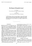

source: “The Westrex 3D StereoDisk System”, C.S. Nelson and J.W. Stafford, Journal of the Audio Engineering Society, Vol. 12, No. 3 (July 1964), pp.178-185.
Even with feedback, the response characteristic is not perfectly flat in velocity.
フィードバックありの状態での Westrex 3C および 3D カッターヘッドの特性。このままだと十分に定速度フラットではない。
この RA-1574-D パワーアンプでは、録音カーブが巧妙なかたちで制御されています。
In the RA-1574-D power amplifier, the recording curve is dexterously controlled.
まず、RA-1574-D 内部のスロットに挿入されたパッシブ LRC プラグインカードにより、30Hz〜1,000Hz の帯域が RIAA カーブ、1,000Hz〜15,000Hz の帯域はフラット(定速度)になるようWestrex 3D カッターヘッド専用で補正します。
First, a passive LRC plug-in card inserted into a slot inside the RA-1574-D corrects the 30Hz to 1,000Hz range to the RIAA curve, and the 1,000Hz to 15,000Hz range to flat (constant velocity), exclusively for the Westrex 3D cutterhead.

source: “The Westrex 3D StereoDisk System”, C.S. Nelson and J.W. Stafford, Journal of the Audio Engineering Society, Vol. 12, No. 3 (July 1964), pp.178-185.
This plug-in card (for Westrex 3D cutterhead) provides constant velocity equalization from 1kHz to 15kHz, and RIAA equalization from 30Hz to 1kHz.
RA-1574-D 用プラグインイコライザカードの回路図。
Westrex 3D カッターヘッドの記録特性を 1kHz 以下を RIAA 特性、1kHz 以上は定速度フラットに整えるもの。
つまり、RIAA 録音特性の時定数のうち 3,180μs(ベースシェルフ)と 318μs(ターンオーバー)は使用するが、75μs(高域プリエンファシス)はなし、という 500R-FLAT カーブです。これは、Buchman=Meyer の光帯法を使うなど、テストカットによる計測・較正用のポジションとなります。
The curve uses the time constants of 3,180μs (bass shelf) and 318μs (turnover) of the RIAA recording characteristic, but without 75μs (high-frequency pre-emphasis), which is so-called “500R-FLAT”. This is for measurement and calibration with test cuts, such as using the Buchman=Meyer light pattern method.
少し横道にそれますが、この「1kHz 以下は RIAA 録音特性、1kHz 以上は定速度フラット」という特性は、JVC TRS-1007、clearaudio CA-TRS-1007、東芝EMI LF-1003(JIS C5507 SR-33)などのテストレコードにも共通した特性(500R-FLAT)です。
To go a little sideways, this “RIAA recording curve below 1kHz, constant velocity flat above 1kHz” is the characteristic (500R-FLAT) shared by frequency test records such as JVC TRS-1007, clearaudio CA-TRS-1007, Toshiba EMI LF-1003(JIS C5507 SR-33) and more.
一方、別の有名なテストレコード DENON XL-7004 およびその再プレスである 日本オーディオ協会 AD-1 は、ターンオーバー周波数 250Hz、重低域ターンオーバー(ベースシェルフ)なし、高域プリエンファシスなし、という特性(250N-FLAT)となっています。
On the other hand, another famous test record such as DENON XL-7004, and its repress Japan Audio Society AD-1, are cut with the following characteristic (250N-FLAT): turnover frequency at 250Hz, no low-bass turnover (bass shelf), no high-frequency pre-emphasis.
これらのテストレコードで中高域がフラット特性になっているのは、RIAA 録音特性のままスイープ信号を記録すると、増幅が強い高域でディスクカッティング時の録音限界を超えてしまうためです。
The reason why the mid and high frequencies are flat in these test records is that, if the sweep signal was recorded with the RIAA recording characteristics, the high frequencies with strong amplification would exceed the recording limit for disc cutting.
話を戻すと、RA-1574-D のパネルに「RIAA IN/OUT」スイッチがあり、IN にすると 1,000Hz〜15,000Hz 帯域の RIAA カーブが追加され、合計で RIAA 録音特性での記録となります。一方 OUT にすると、アンプは完全フラット特性となり、プラグインカードそのままの特性(RIAA 録音特性の1kHz 以上が定速度フラットなもの)となります。
Returning to the topic: there is a “RIAA IN/OUT” switch on the panel of the RA-1574-D. When set to “IN”, RIAA curve in the 1,000Hz to 15,000Hz range is added, resulting in a total recording with RIAA recording characteristic. On the other hand, when set to “OUT”, the amplifier is completely flat, and the plug-in card’s characteristic remain unchanged (i.e. RIAA recording characteristics, except constant-velocity flat above 1kHz).

source: Forum post at The Secret Society of Lathe Trolls, posted by skyonion, Jun. 26, 2016.
RA-1574-D アンプの貴重な内部写真。
左上に「RIAA IN/OUT」スイッチが見える。
左の上から2番目のボードが、録音用プラグインイコライザカード、右下のボードが、モニタ再生用プラグインイコライザカード。
 | microgroove.jp")
source: “The Westrex 3D StereoDisk System”, C.S. Nelson and J.W. Stafford, Journal of the Audio Engineering Society, Vol. 12, No. 3 (July 1964), pp.178-185.
RA-1574-D 回路図より、RIAA IN/OUT スイッチ部分の拡大。
つまり、RIAA 録音カーブの 1kHz より下の録音特性は、各種 Westrex カッターヘッド用に用意されたプラグインカードによって実現され、1kHz より上の録音特性は、RA-1574-D 録音パワーアンプ内の回路によって実現されているわけです。
It clearly shows that, the RIAA recording characteristics below 1kHz are achieved by the plug-in cards dedicated for each Westrex cutterheads, and the RIAA recording characteristic above 1kHz are achieved by the circuitry in the RA-1574-D recording power amplifier.
19.2.7 Westrex RA-1703 Input Amplifier
1960年代末頃に登場したと思われる、オペアンプなど半導体素子を活用した Westrex RA-1700 録音システムも情報が残っています。RA-1702 パワーアンプ、RA-1703 インプットアンプ、RA-1704 フィードバックアンプ、RA-1706 高域減衰アンプ、というシステムです。
Information on the Westrex RA-1700 recording system, which appears to have appeared in the late 1960s and utilizes solid state (semiconductor) parts such as operational amplifiers, also survives. The system consists of: RA-1702 Power Amplifier, RA-1703 Input Amplifier, RA-1704 Feedback Amplifier, RA-1706 High Frequency Reduction Amplifier, etc.

source: “Jack Horowitz and the Scully Lathe” (dekedickerson.com)
Westrex RA-1700 シリーズの貴重なフロント写真
一番上に RA-1702 パワーアンプ x 2、その下に RA-1706 高域減衰アンプ、RA-1703 インプットアンプ、RA-1704 フィードバックアンプが2組ずつ配置。
RA-1703 のパネルには「FLAT/OFF/RIAA」のセレクタが確認できる
このうち、RA-1706 高域減衰アンプが非常に興味深く、少し調べてみました。なんと、エクアドルの 国立工科大学 の1988年に提出された「diseno y construccion de un control con microprocesador para un torno de corte de acetatos master, utilizado en la fabrication de discos fonográficos」(レコード盤製造に使用されるカッティングレースを制御するマイクロプロセッサの設計と制作)という学位論文の中に、RA-1706 の文書が引用されているのを見つけました(笑)
Among these, RA-1706 high frequency reduction amplifier was of great interest to me, so I did a little research. To my surprise, I could find the RA-1706’s document quoted in the thesis for a degree “diseno y construccion de un control con microprocesador para un torno de corte de acetatos master, utilizado en la fabrication de discos fonográficos” (design and construction of a microprocessor control for a master acetate cutting lathe used in the manufacture of phonograph records), published in 1988 at Escuela Politécnica Nacional, Ecuador.

source: Westrex Quad 8 HF Limiter (Reverb.com)
RA-1706 は、オーバーカッティング対策のために、録音ソースの高域部分に適用するリミッタ。適用量に応じて OFF / 1 / 2 / 3 / MAX のポジションがある。

source: Westrex RA 1700 System Instructions (?) Section IX
RA-1706’s output-input characteristics of RA-1706 at various frequencies for the button no.2 condition
RA-1706 のボタン2の場合の、入力レベル(横軸)と出力レベル(縦軸)の特性。
7kHz では +1dB からリミッタがかかり、9kHz では -2dB からリミッタがかかり…と、高域リミッタの特性が読み解ける。
RA-1706 について説明する文書には、「エンジニアの主観的な判断によって適用を判断すべし」という非常に興味深い記載があります。
There is a very interesting paragraph “the use of such equipment demands subjective decisions by the engineers”:
Therefore, the use of a high-frequency reduction amplifier often demands subjective decisions on the part of the technician … and commercial recordings benefit by these decisions. When one is dealing with an art process, no automatic device can replace a man — it can only aid him. Any audio protective device (limiter, compressor, clipper, H.F. reduction amplifier etc.) should be used as little as possible. When used, they should be applied to the smallest degree that produces satisfactory results. The RA1706’s pushbuttons allow choice of degree.
したがって、高周波減衰アンプの使用は、しばしば技術者に主観的な判断を要求する。そして商用録音は、こうした判断によってメリットを得る。芸術的なプロセスを扱う際、いかなる自動装置も人の代わりとはならない。あくまで人の助けになるだけである。 いかなるオーディオ保護装置(リミッタ、コンプレッサ、クリッパ、高域減衰アンプなど)は、可能な限り使用を控え目にすべきである。そして使用する場合には、満足のいく結果が得られる最小の程度にすべきである。RA1706 ではプッシュボタンで(高域減衰の)度合いを選択可能となっている。
Westrex RA 1700 System Instructions (?) Section IXこのような高域減衰アンプが使われていたとしても、下で見る通り、録音カーブ自体は当然 RIAA でした。
As shown below, the recording curve itself was RIAA, even with the use of such high frequency reduction amplifiers.
さて、このシステムでは RA-1703 インプットアンプが録音カーブを司っています。さきほど上で見た RA-1574-D パワーアンプと同様、RIAA 録音カーブの 1kHz 以下の部分と、1kHz 以上の部分は、別々の回路で実装されており、1kHz 以上の部分をオフにして、計測・較正用とするのも同じです。
In this system, the RA-1703 Input Amplifier controls the recording curve. Like the RA-1574-D power amplifier seen above, the portion of the RIAA recording curve below 1kHz and the portion above 1kHz are implemented in separate circuits, and the portion above 1kHz can be turned off for measurement and calibration purposes.

source: “Appendix C: The R.I.A.A. Frequency Response Characteristic for Disc Recording”.
Line AB is the RIAA characteristic of RA-1703, while line AC is the “response with the 75 μs high-frequency emphasis portion of the RIAA curve omitted, and is the response recorded with the switches on the RA1703 amplifiers in their FLAT position”.
Westrex RA-1703 インプットアンプ(RIAA録音イコライザ内蔵)の付属文書より
(A)〜(B) が RIAA 録音特性 (RIAAポジション)、(A)〜(C) は「RIAAカーブのうち 75μs高域増幅部分を割愛したもので、RA1703をFLATポジションにした時の特性」。

source: “Recap for Westrex 1700 lathe cutter amps” (diyaudio.com forum).
bottom-left portion of the schematic is “Constant Velocity Equalizer 98609”, plug-in card,
which equalizes 3,180μs and 318μs of the RIAA recording curve
Westrex RA-1703 の貴重な回路図。リンク先で拡大したものが見られます。
左下が、RIAA の 3,180μs と 318μs 部分をつかさどるプラグイン回路で「Constant Velocity Equalizer 98609」とある
さらに個々のカッターにあわせて可変抵抗と可変コンデンサを微調整すべし、とある
真ん中下が、FLAT/OFF/RIAA 切替スイッチ部分
つまり、この RA-1703 内蔵のディスク録音イコライザも、RIAA 録音特性の 3,180μs(ベースシェルフ)と 318μs(ターンオーバー)を実現する回路と、75μs(高域プリエンファシス)を実現する回路が独立しており、前者は「Constant Velocity Equalizer 98609」というプラグインカードで実装、後者はアンプ内の回路で ON/OFF できるような仕組みが採用されていたことにになります。
In other words, the RA-1703’s built-in recording equalizer also had two independent circuits, one to realize the RIAA recording characteristics of 3,180μs (bass shelf) and 318μs (turnover), and the other to realize 75μs (high-frequency pre-emphasis). The former was implemented with a plug-in card called “Constant Velocity Equalizer 98609”, while the latter could be turned on and off by the circuitry in the amplifier.
19.2.8 Neumann LV60 Power Amplifier
続いて、米 Westrex と並び称され、1970年代までにはデファクトスタンダードの地位を獲得した Neumann が 1950年代末に出したと言われるモノーラル録音パワーアンプ LV-60 をみてみましょう。Neumann ES-59 モノーラルカッターヘッドや SX-15 / SX-45 ステレオカッターヘッドなどと組み合わせることを念頭においたアンプです(ステレオ録音時には当然 LV-60 パワーアンプ x 2 が必要)。米国では Gotham Audio 社が販売していました。
Next, let’s take a look at the LV-60 monaural recording power amplifier, which is said to have been released in the late 1950s by Neumann, a company that was considered the de facto standard by the 1970s, along with Westrex. For stereo recording, two LV-60s are required, of course. In the U.S., it was sold by Gotham Audio.

source: 稀世珍品 Neumann LV60 復原記.
ムーヴィングコイルフィードバックカッター ES-59 は、30Hz〜24,000Hz でほぼフラットな記録特性を実現しています。
The ES-59 moving coil feedback cutter provides nearly flat response from 30Hz to 24,000Hz.

source: “New Products from 1966”, Gotham Audio Corporation.
一番上のグラフが、ES-59 フィードバックカッターの記録特性。
ES-59 に組み合わせる LV-60 パワーアンプによって録音EQが適用されます。しかし、ドイツ製だけあって、ドイツ国内規格の事情にも対応した構成となっています。
The recording equalization is applied by the LV-60 power amplifier combined with the ES-59. However, because it was made in Germany, it is also configured to meet the circumstances of German domestic standards.
LV-60 がデフォルトで対応可能な録音EQカーブは、RIAA、DIN、計測・較正用のFLAT となっています。しかも、ダイアル式などのスイッチではなく、アンプ前面のパネルを外すと交換可能なプラグインソケットタイプとなっています。
The recording EQ curves that the LV-60 can support by default are: RIAA, DIN, and FLAT (for measurement and calibration). Moreover, they are not dial-type switches, but plug-in type that can be replaced by removing the panel on the front of the amplifier.

source: “New Products from 1966”, Gotham Audio Corporation.
LV-60 のプラグイン式録音EQの記録特性グラフ。上から DIN、RIAA、Cal.(計測較正用、1kHz 以上はフラット)
上のグラフからも分かる通り、RIAA 録音特性と DIN 録音特性は、高域プリエンファシスのみが異なります。RIAA(500R-13.7)の高域プリエンファシスの時定数は 75μs、DIN(500R-10.5)は 50μsです。そして、下の回路図を見ると、プラグイン回路は高域プリエンファシス部分のみのパラメータを変更しているように読み取れます。
As can be seen from the graph above, the RIAA and DIN recording characteristics differ only in the high-frequency pre-emphasis portion: the time constant for high-frequency pre-emphasis for RIAA (500R-13.7) is 75μs, while for DIN (500R-10.5) being 50μs. And looking at the schematic below, it reads as if the plug-in circuit changes the parameters only for the high-frequency pre-emphasis portion.

source: “Neumann’s Last Pole”, Pspatial Audio.
Neumann LV-60 の回路図より、プラグイン録音EQ部分を拡大したもの。
RIAA用とDIN用では、4番ピンと6番ピンの間のコンデンサのみが異なる、と読み解ける
it reads that only the capacitor(s) between the pin 4 and pin 6 are different
 | microgroove.jp")
source: EL156 PushPull >< Neumann LV-60 >< Killer (tubuguru.eu)
the plug-in socket in the bottom center is for changing recording EQs
LV-60 フロントパネルを外した貴重な内部写真
写真中央下に見えるのが、録音EQ設定用プラグインソケット
つまり、Neumann LV-60 においても、録音カーブの高域プリエンファシス部分はプラグイン回路で微調整可能、それ以外の部分(318μs と 3,180μs に相当)は、LV-60 本体内の固定回路でイコライズを実現していることになります。
So, again in the Neumann LV-60, the high-frequency pre-emphasis portion of the recording curve can be fine-tuned by the plug-in circuit, while the other portion (corresponding to 318μs and 3,180μs) are equalized by a fixed circuit in the LV-60 itself.
Neumann LV-60 録音パワーアンプの RIAA / DIN 録音特性に呼応するように、再生用の Neumann WV-2 ステレオフォノプリアンプでも、RIAA / DIN 再生ポジションが用意されていることが、1958年4月当時の WV-2 パンフレット から確認できます。
According to the Apr. 1958 brochure of the Neumann WV-2 stereo phono preamplifier, it had RIAA/DIN playback positions, which directly correspond to the RIAA/DIN recording EQ positions of the LV-60 recording power amplifier.

19.2.9 Neumann VE-66S / VG-66 Amplifier System
1960年代後半になると、真空管ではなくオペアンプなど半導体素子を活用した録音システム Neumann VE-66S / VG-66 が登場します。
In the late 1960s, Neumann VE-66S / VG-66, utilizing solid state (semiconductor) parts such as operational amplifiers, was released.

モノーラル用 ES-59 や、ステレオ用 SX-15 / SX-45 といったカッターヘッドと、VMS-66 カッティングレースとの組み合わせを想定した VE-66S / VG-66 システムには、カッターヘッドイコライザ CE-66 と、録音イコライザ SE-66 が含まれています。
The VE-66S / VG-66 system — designed for use with cutterheads such as the ES-59 (mono) or the SX-15 / SX-45 (stereo) and the VMS-66 cutting lathe — includes the CE-66 cutterhead equalizer and the SE-66 recording equalizer.
 | microgroove.jp")
source: Neumann VG66 1960-1970 (Reverb.com)
the center units: Cutting Equalizer CE-66;
on the left: SE-66 Recording Equalizer (RIAA), with “RIAA IN/OUT” slider switch.
中央にあるのが CE-66 カッティングイコライザ、これでフィードバックカッターの特性をフラットに微調整する
その左にあるのが SE-66 録音イコライザ、RIAA 録音特性を提供。RIAA IN/OUT スライド式スイッチが確認できる。
1962年に DIN (CCIR) 録音特性が RIAA 録音特性と同一になったため、もはや録音EQ切り替え用プラグインは存在していません。SE-66 録音イコライザ(当時の回路図 左半分 と 右半分)は、オペアンプを使った固定RC回路による RIAA 録音イコライザでした。一方、SE-66 フロントパネルには、計測・較正用の RIAA IN/OUT スイッチがあります。
Since the DIN (CCIR) recording characteristics became identical to the RIAA recording characteristics in 1962, there is no longer a plug-in for switching the recording characteristics. The SE-66 recording equalizer (circuit diagram: left half and right half) was an RIAA recording equalizer with a fixed RC circuit using operational amplifiers. On the other hand, SE-66’s front panel has an “RIAA IN/OUT” switch for measurement and calibration.
19.2.10 Ortofon GO-741 Cutting Amplifier
1975年頃に登場した、Ortofon GO-741 は、Ortofon DSS-731(クワドロフォニック用カッターヘッド)、Ortofon DSS-732(ステレオ用カッターヘッド)向けに用意されたカッティングアンプです。A0089 入力アンプ、A0027/2 イコライザ、A0060/3 フィードバックアンプ、A0054/3 ドライバアンプ、A0061/4 パワーアンプなどのボードユニットから構成されています。
The Ortofon GO-741, introduced around 1975, is a cutting amplifier for the Ortofon DSS-731 (quadrophonic cutterhead) and Ortofon DS-732 (stereophonic cutterhead). It consists of board units including the A0089 Input Amplifier, A0027/2 Equalizer, A0060/3 Feedback Amplifier, A0054/3 Driver Amplifier, and A0061/4 Power Amplifier.

source: etec electronic engineering: Ortofon vintage documents.
GO 741 がカッティングアンプ、GE 741 が電源ユニット

source: “プレーヤー・システムとその活きた使い方”, 無線と実験 / 初歩のラジオ 別冊, 井上敏也監修, 誠文堂新光社, 1977
Ortofon GO-741 と組み合わせて使う、CD-4 用カッターヘッド DSS-731 の記録特性
Frequency responses of the Ortofon DSS-731 CD-4 Cutterhead, with and without feedback
このうち、録音カーブに関係するのは A0089 入力アンプボードで、オペアンプが使われたRC型です。下の写真では、最も左に垂直に差し込まれているボードが A0089 になります。
Of these, the one related to the recording curve is the A0089 Input Amplifier board, which is an RC type with an operational amplifier. In the photo below, the A0089 board is plugged vertically into the leftmost position.

source: Forum post at The Secret Society of Lathe Trolls, posted by Dub Bull, Jun. 25, 2021.
Ortofon GO 741 内の貴重な内部写真。
多くのアンプモジュールが並んでおり、最も左のボードが A0089 Input Amplifier。
この入力アンプの果たす役割については、GO 741 マニュアルに記載があります。
The role played by this input amplifier is described in the GO-741 instruction manual.

source: Ortofon GO 741 Cutting Amplifier Instruction Manual, Forum post at diyaudio.com, posted by gpapag, on Mar. 3, 2019.
The purpose of the Input Amplifier is:
- To convert the available input program signal into a suitable level for the summing with the motional feedback signal in the proceeding Feed Back Amplifier.
- To provide the treble frequency pre-emphasis according to the standards (IEC, RIAA etc.).
- To provide the flat recording characteristics below 50 Hz also required by the standards.
- To provide together with the proceeding Feed Back Amplifier the normalised roll off between 500 Hz and 50 Hz.
入力アンプの目的は以下の通りである。
- 入力プログラム信号を、後段のフィードバックアンプのモーショナルフィードバック信号との和に適したレベルに変換する。
- 標準規格(IEC, RIAA 等)に準拠した高域プリエンファシスを提供する。
- 同じく標準規格に準拠した 50Hz 以下の特性(ベースシェルフ)を提供する。
- 後段のフィードバックアンプと共に、50Hz〜500Hzのロールオフを提供する。
つまり、GO-741 においては、ベースシェルフ(3,180μs)と高域プリエンファシス(75μs)は、A0089 入力アンプモジュール によって提供される一方、ターンオーバー500Hz(時定数318μs)は、A0089 入力アンプと A0060/3 フィードバックアンプの組み合わせによって提供される、ということになります。
This means that, in GO-741, the bass shelf (3,180μs) and high-frequency pre-emphasis (75μs) are provided by the A0089 input amplifier module, while the turnover of 500Hz (time constant 318μs) is provided by the combination of the A0089 input amplifier module and the A0060/3 feedback amplifier module.
このうち、高域プリエンファシス部分(75μs)は、GO-741 本体の「TEST」ボタンを押すと無効になり、1kHz 以上が定速度フラットである計測・較正用のカーブ(500R-FLAT)になります。このスイッチは、A0089 入力アンプの回路上にある FET スイッチと連動しており、回路をバイパスすることで実現されています。
The high-frequency pre-emphasis portion (75μs) can be disabled by pressing the “TEST” button on the GO-741 main unit, and the recording curve becomes the one for measurement and calibration (500R-FLAT), which is constant velocity flat above 1kHz. This switch works in conjunction with the FET switch on the circuit of the A0089 input amplifier, by bypassing the circuit.
GO-741 のさらに興味深い機能として、ハーフスピードマスタリング があります。ハーフスピードマスタリング対応の入力アンプ A0089/S がラインアップされており、本体の「HALF SPEED」ボタンを押すと、すべての時定数が2倍になることにより、ターンオーバー周波数は 500Hz から 250Hz に、高域プリエンファシスの時定数は 75μsから 150μsに変更されます。さらに、重低域ターンオーバー(ベースシェルフ)がキャンセルされます。
A further interesting feature of the GO-741 is half-speed mastering. The variation of A0089 input amplifier, A0089/S, supports half-speed mastering. By pressing the “HALF SPEED” button on the unit, it doubles all time constants: thereby changing the turnover frequency from 500Hz to 250Hz, and the high-frequency pre-emphasis time constant from 75μs to 150μs, and canceling the low-bass turnover (bass shelf).
19.3 Thought Experiment: To Accomplish non-RIAA with Those Equipment
全てを網羅することはできませんでした(特に Neumann SAL-74 カッティングアンプに触れなかったのは心残りです)が、1950年代〜1970年代に使われていたさまざまな録音システムをみてきました。
We have looked at the various recording systems used from the 1950s to the 1970s, although I couldn’t cover all of them. I regret that I did not mention the Neumann SAL-74 cutting amplifier.
 | microgroove.jp")
source: Neumann VMS 70 Fully restored (Reverb.com)
SAL-74B Drive Amplifiers: cutting equalizers in the middle have “RIAA IN/OUT” switch
VMS-70 システムの SAL-74B ドライブアンプ群
真ん中のカッティングイコライザ部分に「RIAA IN/OUT」スイッチが見える
さて、ここで、少しへんてこりんな思考実験 をしてみましょう。自分でも全くバカらしいと分かっているのですが、あえてやります(笑)
Now, let’s try a slightly weird thought experiment. I know it is totally silly, but I’m going to do it anyway 🙂
RIAA 標準規格策定後、いままでみてきたような 当時の録音システムで、RIAA 録音特性「以外」のカーブでカッティングを実現するには、どうしたらいいでしょうか。
On the various recording systems of the time, how can we (you) achieve cutting with a curve other than the RIAA recording characteristic, after the standardization of the RIAA recording characteristcs?
セクション 19.2.1 の Cinema Engineering Type 7095、あるいは セクション 19.2.4 の Westrex RA-1514 のような、録音チェーンに挿入されるタイプのパッシブLRC録音イコライザユニットの場合はどうでしょうか。これらの LCR EQ ユニットを取り外し、別の録音特性を実現するユニットに交換する必要があります(ただし、1955年以降、そのような非RIAA録音イコライザユニットは米国でプロフェッショナル向けに製造販売されていませんでしたから、自力で作る必要があります)。
What about passive LRC recording equalizer units, such as Cinema Engineering Type 7095 (Section 19.2.1) or the Westrex RA-1514 (Section 19.2.4), that are inserted into the recording chain? You would need to remove these LCR passive EQ units and replace them with units that achieve different recording characteristics. But you would have to make your own, since such non-RIAA recording equalizer units have not been manufactured and sold for professional use in the United States since 1955.
セクション 19.2.2 でみた、Gotham PFB-150WA 録音アンプの場合はどうでしょう。おそらくは、アンプに内蔵された録音イコライザをキャンセルし、すなわち「FLAT」ポジションにして、別途録音イコライザを録音チェーンに挿入する必要があります(ただし、入力損失を考えると、品質的なデメリットが大きそう)。あるいは、PFB-150WA 内部の録音EQ回路を改造するしかなさそうです。
What about the Gotham PFB-150WA recording amplifier (Section 19.2.2) ? Perhaps the recording amplifier built into the amplifier would need to be canceled, i.e. set to the “FLAT” position, and a separate recording equalizer would need to be inserted into the recording chain (but given the insertion loss, the quality disadvantage would not seem negligible). Alternatively, the recording EQ circuit inside the PFB-150WA would have to be modified.
セクション 19.2.3 の Fairchild 641 システムの場合は、644 パワーアンプを改造して高域プリエンファシスとベースシェルフを変更し、さらに 643 ベータアンプを改造してターンオーバーを変更する必要があります。
For the Fairchild 641 system (Section 19.2.3), the 644 Power Amplifier would need to be modified to change the high-frequency pre-emphasis and bass shelf, and the 643 Beta Amplifier must also be modified to change the turnover.
セクション 19.2.5 でみた Westrex RA-1574-B システムで、RA-1615-A ではなく RA-1617-A を使うパターンでは、RA-1617-A 自体を改造する必要があります。RA-1615-A を使うパターンでは、上述の Cinema Engineering Type 7095 の時と同じです。
For the Westrex RA-1574-B system (Section 19.2.5) the pattern of using RA-1617-A instead of RA-1615-A would require modification to the RA-1617-A itself. The pattern for using the RA-1615-A is the same as for the Cinema Engineering Type 7095 described above.
セクション 19.2.6 でみた、Westrex RA-1574-D システムではどうでしょう。RIAA 録音特性の 1kHz 以下をつかさどるプラグインカードを改造し、さらに RA-1574-D アンプ内の RIAA 録音特性の 1kHz 以上をつかさどる回路を改造する必要があります。あるいは、Westrex 謹製のプラグインカードを外し、3Dカッターで全帯域フラットとなるように補正する独自カードに差し替えた上で、別途パッシブLRC録音イコライザユニットをシグナルパスに挿入する必要があります。
What about the Westrex RA-1574-D system (Section 19.2.6) ? You would need to modify the plug-in card responsible for the RIAA recording characteristics below 1kHz, and also modify the circuitry in the RA-1574-D amplifier itself which is responsible for the RIAA recording characteristics above 1kHz. Alternatively, the Westrex plug-in card would need to be removed and replaced with a proprietary card that uses a 3D cutter to correct for full bandwidth flatness, and a passive LRC recording equalizer unit would need to be inserted into the signal path.
同様に、セクション 19.2.7 でみた、Westrex RA-1703 でも、Constant Velocity Equalizer 98609 を改造してターンオーバーとベースシェルフを変更し、さらに RA-1703 メイン回路内の高域プリエンファシス部分の回路を改造する必要があります。あるいは、RA-1703 のスイッチを OFF ポジションにし、別途録音イコライザをシグナルチェーンに挿入する必要があります。
Likewise, the Westrex RA-1703 (Section 19.2.7) would require modifications to the Constant Velocity Equalizer 98609 to change the turnover and bass shelf, as well as modifications to the high-frequency pre-emphasis portion of the circuit in the RA-1703 main circuit. Alternatively, the RA-1703’s switch would need to be at OFF position, and would need another recording equalizer to be inserted in the signal chain.
セクション 19.2.8 でみた、Neumann LV-60 の場合は、高域プリエンファシス部分は、本体のカバーを外してアクセス可能なプラグイン部分(コンデンサのみで実現)を所望のカーブ用に用意するだけですから、比較的簡単に変更できそうです。ただし、ターンオーバーやベースシェルフは、LV-60 本体の回路を改造する必要がありますね。
In the case of the Neumann LV-60 (Section 19.2.8), the high-frequency pre-emphasis portion would be relatively easy to modify, since the plug-in module (realized only with capacitors), which is accessible by removing the cover of the main unit, is simply prepared for the desired curve. However, for the turnover and bass shelf, you would need to modify the circuitry of the LV-60 itself.
セクション 19.2.9 でみた、Neumann VE-66S / VG-66 システムの場合は、SE-66 録音イコライザユニットを改造するか、交換する必要があります。ただし、Neumann は SE-66 に代わる非 RIAA 録音特性の録音ユニットを(当然)出していませんでした。
In the case of Neumann VE-66S / VG-66 System (Section 19.2.9), SE-66 Recording Equalizer Unit would need to be modified, or it would be replaced with other equalizers that does non-RIAA recording characteristic (although Neumann never have offered such non-RIAA recording equalizer units, of course).
セクション 19.2.10 でみた、Ortofon GO-741 アンプではどうでしょう。入力アンプボード A0089 を改造する必要があるほか、フィードバックアンプボード A0060/3 の改造もあわせて必要になります。また、ハーフスピードカッティング用のパラメータをつかさどるコンデンサや抵抗も全て変更する必要があります。
What about the Ortofon GO-741 amplifier (Section 19.2.10) ? The A0089 Input Amplifier board would need to be modified, as well as the A0060/3 Feedback Amplifier board. Also, all the capacitors and resistors that control the parameters for half-speed cutting would need to be modified as well.
米国を代表する優れた録音エンジニア5名が策定し、米全レーベルが合意して承認され、業界標準となった RIAA 録音特性を、ここまで大変な作業をして、わざわざ変更することは現実的でしょうか?
Is it realistic and/or practical to go to such great lengths to change the RIAA Recording Characteristics, which were formulated by five of the best recording engineers in the U.S. at the time, agreed and approved by all U.S. labels, and have become the industry standard?
確かに、「技術的には可能」です。小規模スタジオの機材の少数セットで行うなら、まだ分かります。
Actually, it is “technically possible”. If it was done with a small set of equipment in a small independent studio, it would be still understandable.
It is not impossible to adjust the RIAA curve inside. I once saw a Gotham amp where they increased the low-end for cutting jukebox records.
(アンプ内部で実装された)RIAA カーブの調整は不可能ではない。ジュークボックス用レコードをカッティングするためにローエンドを上げるよう改造された Gotham のアンプを見たことがある。
quoted from the email written by Nicholas Bergh to me on November 20, 2023しかし、多数のマスタリング機材を全米各地に持つメジャーレーベルが、全ての機材を同等スペックに独自改造することは非現実的に思えます。もし、それを行うのであれば、機材メーカに特注して、別録音特性用のカスタムモデルをオーダーするのが現実的です(が、そのような機材の存在は知られていません)。
However, it seems unrealistic and impractical for major labels (with many mastering facilities throughout the United States) to modify all of its equipment to equivalent specifications. If they were to do so, it would be more practical to special order custom models from equipment manufacturers for different recording characteristics (but such custom equipment is not known to exist).
こんな大変な作業をしなくても、ミックスダウンしマスタリングしてカッティング用マスターテープを作る際、可変イコライザやコンプレッサ / リミッタなどを使って自在に音作りは可能です。そちらの音作りの方が主でしょう。
It was possible to freely create sounds without such a difficult process, using a variable equalizer, compressor, limiter, etc., when mixing down, mastering, and making a master tape for cutting. And such sound creation was probably more important.
そもそも録音カーブの選定は(78回転盤の時代とは異なり)音作りが目的ではありませんでした。また、カッティング時の技術的制約などから、RIAA 録音特性を使いつつ、上で見た Westrex RA-1706 のような高度なローパスフィルタを使ってカッティング時に高域成分を意図的に減衰させることは一般的なプラクティスでした。
In the first place, the selection of the recording curves was not for the purpose of sound production (unlike in the era of 78 rpms). Also, due to technical limitation at the time of cutting, it was common practice to intentionally attenuate high-frequency components by using a sophisticated low-pass filter such as the Westrex RA-1706 during the cuttings, while using the RIAA recording characteristics for disc recording.
標準規格である録音特性を変更せずとも、録音エンジニアが腕を振るう余地は多分にあり、また録音特性が統一されることで、余計な変数(可変要素)がひとつ減るので、技術的にも取り組みやすくなるものです。
There was plenty of room for the recording engineers to exercise his/her skills without having to change the standard recording characteristics. Also, the standardization of recording characteristics reduced one extra variable, making it easier to work with from a technical standpoint.
さらに、これらの録音システム内蔵のモニタ用再生イコライザは RIAA でした。RIAA 特性で再生することを前提にカッティングされたものをチェックしていたわけです(録音システム内蔵のモニタ用再生イコライザも改造されていた事実が判明しない限り)。
Besides, the monitor equalizer in such recording systems were all RIAA, which means that the engineers were checking the results of the cuttings, intended to be played back with the RIAA reproducing characteristics (unless we find any evidence of the monitor playback equalizers being also modified at the time).
19.3.1 So RIAA would virtually be the only choice
78回転盤時代のように録音カーブも音作りの一貫だった時代から、Pultec EQP-1A などの可変イコライザ(Pt.17 セクション 17.4 参照)、イコライザ、ローパスフィルタ、ハイパスフィルタ、コンプレッサ、リミッタなどさまざまな機器の登場により、録音カーブと独立した自在な音作りが可能になった時代へ。
The era of 78 rpm recordings, in which the recording curve was one of the integral part of the sound making process, gave way to an era in which the advent of variable equalizers such as Pultec EQP-1A (see: Pt.17 Section 17.4) made possible flexible sound making, independent of the recording curve. Such equipment also included low-pass filter, high-pass filter, compressor, limiter, etc.
ホットスタイラス技術(Pt. 12 セクション 12.2.1)やフィードバックカッター(Pt. 18 セクション 18.1)の登場により、ますます高品質化・高音質化を狙えるようになった、ディスク録音システムの時代へ。
The advent of hot stylus technology (see: Pt.12 Section 12.2.1) and feedback cutters (see: Pt.18 Section 18.1) has ushered in the era of disc recording systems that can aim for increasingly higher quality and better sound.
1939年の RCA/NBC による Orthacoustic 録音特性(Pt. 5 セクション 5.2.1〜5.2.3)から 1942/1949 NAB 録音規格(Pt.8 および Pt.10)、そして(ベースシェルフ以外は)Columbia LP カーブ(Pt.12 セクション 12.2.3)へ、と引き継がれ長年使われてきた、100μs プリエンファシスの録音カーブ。この高域増幅は過剰でデメリットが多すぎるので、もっと弱めるべき、と長年議論され続け、その結果やっと1954年に米レコード業界全体の合意で策定できた RIAA 録音再生特性という 75μs プリエンファシスの標準規格の時代へ。
From “100μs” to “75μs”: the 1939 RCA/NBC Orthacoustic recording characteristics (Pt.5 Section 5.2.1 to 5.2.3) and the 1942/1949 NAB Recording Standards (Pt.8 and Pt.10), followed by the Columbia LP Curve (Pt.12 Section 12.2.3), all of which utilized 100μs high-frequency pre-emphasis, that has been used for many years. It also had been argued for many years that the excessive high-frequency pre-emphasis had many disadvantages and should be lowered. As a result, 1953 NARTB / 1954 new AES / 1954 RIAA adopted the 75μs high-frequency preemphasis.
RIAA特性の策定を受けて、民生用再生機器メーカは、再生カーブは RIAA 一択で製造できるようになりました。もちろん移行期には、古いレコード再生用に可変再生フォノイコ内蔵のアンプはありましたし、好事家向けやアーカイバル目的で、古いレコード向けの可変再生フォノイコは現在でも存在していますが。
With the formulation of the RIAA Standards, consumer reproducing equipment manufacturers were able to produce only RIAA reproducing characteristic into consideration. Of course, during the transition period, there were amplifiers with built-in variable playback phono EQs for reproducing old records. Also, such variable phono preamps for old records still exist today for audio lovers and for. archival purposes.
プロ用録音機器メーカも、録音特性は 1953 NARTB = RIAA 一択へと移行していきました。その上で、現場のエンジニアは Pultec EQP-1A などの可変イコライザ、Universal Audio 1176 / 175B、Fairchild 660 / 670 などのリミッタ、RCA BA-6A などのコンプレッサ、その他にもリヴァーブなど、多種多様な機材を駆使して独自の音作りを行っていきました。カッティング時に Westrex RA-1706 高域減衰アンプのようなローパスフィルタを使うこともありました。
Professional recording equipment manufacturers also shifted to a single choice for recording characteristics: 1953 NARTB = RIAA. On top of that, engineers in the field utilized a wide variety of equipment to creat their own sounds, including variable equalizers such as the Pultec EQP-1A, limiters such as the Universal Audio 1176 / 175B and Fairchild 660 / 670, compressors such as the RCA BA-6A, and reverbs. HF Reduction Amplifier (intelligent low-pass filter) such as Westrex RA-1706 was sometimes utilized.
すべて、RIAA 再生特性で再生されることを前提として、です。
Still, the created sound is assumed to be played back with the RIAA reproducing characteristics.
あとは、いつ RIAA 録音特性に移行するか、つまり、いつ録音機材の回路を修正したり、録音機材を新しいものに差し替えるか、の問題でした。
So it was just a matter of when to move to RIAA recording characteristics, i.e. when to modify the circuitry in the recording equipment of replace it with new recording equipment.
使っている機材のリプレースや設定変更に躊躇していた、これが一部レーベルで RIAA への移行を遅らせた主要因であり、決して「RIAA にはしたくない、他のカーブの方がいいんだ」という意図ではなかった、そのように考える方が、全てを自然に説明できると考えるのです。
I think it would be a more natural explanation for all of these to assume that the hesitation to replace or change the configuration of the equipment they were using was the main reason why some labels delayed the transition to RIAA, and never the intention of “we don’t want to go RIAA — we prefer other recording curve(s)!”
19.4 The summary of what I got this time / 自分なりのまとめ
Pt.0 公開から1年2ヶ月、思えば遠くに来たものです。やっとこさ、RIAA 策定直後の時代に到達しました。
After a year and two months since I published Pt.0 of this entire article, I have finally reached the period after the formulation of the RIAA Standard — I (we) have come this far.
当時の録音アンプの回路図や取説を探すことになるとは思っていませんでしたが、それにしてもたくさん勉強になりました。
I did not expect to find schematics and instruction manuals for the recording amplifiers of that time, but anyway I could learn a lot from them.
さてさて、今回の内容をざっくりまとめると、こんな感じでしょうか。
…so, the rough summary of my understanding in this Pt.19 article would be something like this:
RIAA 規格策定後、民生用再生システムだけではなく、プロ用録音システムも、ディスク録音は RIAA 特性を前提としたものに変わっていった。
After the formulation of the RIAA Standards, not only consumer reproducing systems but also professional recording systems changed to meet the RIAA Recording/Reproducing Characteristic for disc recording.
1950年代〜1970年代のさまざまなディスク録音システムの回路図や取説を調査してみると、そのほとんどがアンプ内に巧妙な仕組みで RIAA 録音イコライザ回路を持っていることが分かった。また、アンプ内のモニタ用再生イコライザ回路も RIAA だった。
A study of many schematics and instruction manuals for various disc recording systems from the 1950s to 1970s revealed that, most of them had RIAA recording equalizer circuits inside the amplifiers dexterously. Also, the monitor playback amplifiers built in these systems had RIAA reproducing EQ circuits.
これらの録音システムでの RIAA 以外の録音特性の適用は、技術的には不可能でないものの、非現実的であるという感想を持った。
The construction of these recording systems seemed (for me) to make it virtually impractical to change the RIAA recording characteristics to others, although it was “technically possible”.
RIAA 録音特性を使いつつも、リミッタやコンプレッサなどを使い、低域を増幅し、高域を減衰させる特性でカッティングするというプラクティスは、ジュークボックス向けなど主に45回転盤用に広く行われていた。Fairchild Model 644 カッティングアンプは、それ専用のポジションも備えていた。
The practice of using a limiter or compressor to amplify the low frequencies and attenuate the high frequencies, while using the RIAA recording characteristic, was widely common for 45 rpms, especially for jukeboxes. Fairchild Model 644 amplifier had such a recording EQ position dedicated to this purpose.
その他、Westrex RA-1700 録音システムの RA-1706 のように、カッティング時に高域減衰するユニットも広く使われていた。
Other example was the Westrex RA-1706 High Frequency Reduction Amplifier (an intelligent low-pass equalizer unit for the RA-1700 System), that was widely used in the recording chain at the time.
次回は、1954年 RIAA 録音再生標準規格の策定後、米国の各レーベルがどのように対応していったのか、その足跡を追っていきます。
My next post will feature the situation of how the industry and each label reacted to the standardization, after the RIAA Standards were formulated in 1954.
» 続き / Sequel: “Things I learned on Phono EQ curves, Pt.20” »